


Sudden load current surges (eg. Due to motor starting) on a generator causes a corresponding change in its output voltage. This is due to an internal voltage drop in the generator winding and effect is called voltage dip. Similarly, load shedding will produce an over voltage at bus bar.
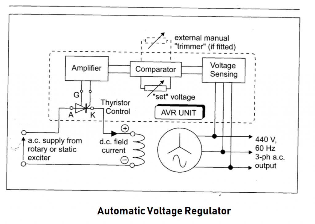
AVR is necessary to regulate/rapidly correct such voltage changes. The AVR senses the generator output voltage and acts to change the field current to maintain the voltage at its set value.
AVR maintains the generator O/P voltage + or – 2.5% of its set value over the load range. The AVR senses and alter field current. A manual/ hand trimmer regulator is fitted on generator control panel to set voltage level. The controlling circuit for a modern AVR consists of transformers, rectifiers, zener diode, transisters and thyristers. These are mounted in one or more circuit either at switchboard or at generator panel.
The voltage sensing unit transforms down, rectifier and smooth the generator output voltage. This produces a low volt d.c. signal that is proportional to a.c. generator voltage This actual d.c. signal is compared with a set d.c. value produced by reference circuit of zener diode and resistors.
An error signal output from comparator is then amplified and made suitable for driving the field current regulating thyristors. The thyristors is a device which rectifies and regulate the generator field current.
Static Automatic Voltage Regulator
- The availability of a transformed and rectified power supply from the alternator output makes possible the matching of it directly against an electronic reference in the static AVR.
- The direct current obtained from the alternator output is applied to a bridge which has fixed resistance on two arms and variable resistances on the other two.
- The zener operates in the reverse breakdown mode, having been manufactured with a zener breakdown voltage of very low value. Voltage remains constant once breakdown has occurred regardless of change in current.
- This implies change in applied voltage, while not affecting voltage across the diode, will cause a change in resistance which permits change in current.
- The imbalance of resistances in wheatstone bridge changes the flow pattern and produces in the voltage measuring bridge an error signal.
- The error signal can be amplified and used to control alternator excitation in a number of ways.
- This it can control the firing angle of thyristors through a triggering circuit to give the desired voltage in the brushless alternator.
- It can be used in the statically excited alternator to connect small errors through a magnetic amplifier arrangement. The error signal can also been amplified through transistors in series, for excitation control.
AVR Safeties
- Fuse in diode circuit to prevent shorting between phases when diode fails.
- By pass resistor across field coils to prevent back flow current.
- Some means of tripping the circuit breaker in case of short circuit 3phase capacitor bank.
Purpose of AVR
- Better load sharing stability in parallel operation.
- Quick response time with voltage stability.
- Over voltage /Under voltage alarm trips.
- AVR senses the generator output voltage and acts to alter the excitation so that generator voltage is maintained within + or – 2.5% of its stated value.
- Transient voltage dip should be within 15% and should be recovered within 1.5sec.
- AVR type – Error operated
Functional type
Process of voltage build up (self excited shunt generator)
Voltage build up – Gradual increase in generator voltage to its max. value after the generator is stared from rest.
The shunt generator utilises the principle of self excitation. If the field system has residual magnetism then rotation of the armature will generate some small emf. This emf will cause a field current which will produce more flux which in turn cause more emf. Hence more field current, more flux and emf to give a continuous building up condition. The voltage continuous to rise and becomes steady when the voltage drop arises the field equals the terminal voltage.
The field current must be in correct direction through the field coil to assist the build up of the voltage against the residual flux.
Condition necessary for self excitation
There must be residual magnetism sufficient enough to generate a small emf when the armature rotated at correct speed.
The shunt field circuit must be continuous and so connected that current flow will cause a flux to build up to assist the original residual flux.
The shunt field circuit resistance must be less than the critical resistance as determined from the open circuit characteristics when machine running at particular speed.


 REQUIREMENTS")