

In this article we will discuss the following basics components of FRAMO system on board 1. Speed Torque controller 2. Pump Remote control system 3. Heating and Venting 4. Oil Filling Procedure, so lets start,
1. FRAMO Speed Torque Controllers (STC)
These are divided in two groups: 1. STC integrated on a pump top plate, ref. fig. 1. 2 . STC separately mounted valves, ref. fig. 2.
Nomenclature for STC valve is as follows
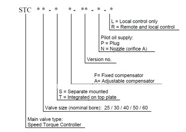
In below pic you can see STC main parts
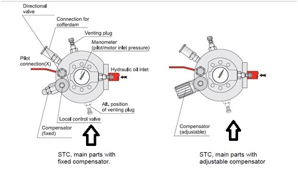
Pilot oil usually externally through pilot connection X (orifice A plugged). For most FRAMO Speed Torque Controllers integrated on top plate, equipment for purging of the cofferdam are built into the valve
For all valves delivered after January 2002, a last chance filter (strainer) is included in pilo tconnection, to reduce possibility of valve failure due to particles.
2. OPERATING INFORMATION
FRAMO Speed Torque Controller, STC, is designed to control the discharge from centrifugal pumps powered by a common ring main hydraulic system.
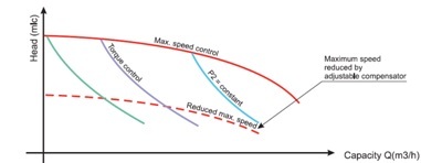
The valve has three main functions, ref. fig. 4:
1. Torque Control (TC).
The valve is used to control the torque of the hydraulic motor independent of inlet pressure (P1). The local control valve with hand wheel regulates the pilot pressure and thereby the inlet pressure to the motor (P2). This can also be done by means of a remote control valve.
2. Maximum Speed Control (max. SC).
The valve limits the oil flow to the hydraulic motor. This function overrides the TC function. This can be observed during certain discharge situations: Any attempt to Increase motor inlet pressure P2 by turning the local, or remote, control valve against maximum position, or by increasing inlet pressure P1, will be ignored by the STC valve.
Some valves are delivered with an adjustable compensator. By using this valve, maximum speed can be reduced to approx. 65 % of specified maximum speed. Maximum speed setting can only be regulated locally. Turn CCW to reduce maximum speed. Turn CW until hand-wheel stops, to adjust back to specified maximum speed.
The adjustable compensator is used to reduce maximum speed during stripping, tank cleaning and other pump operations where maximum speed/maximum discharge head is not required.
3. Closing.
The valve will close off the oil flow when the difference between pilot pressure and return pressure is below appr. 10 bar.
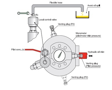
Venting of the valve
Any air pockets remaining inside the valve may cause malfunction. Vent by slightly unscrewing the two venting plugs, at minimum system pressure. A flexible hose with inner diameter 7 mm to be connected as shown, to prevent oil spill.
The local control valve (pressure relief) also needs to be vented. There is a separate venting plug for this purpose. Return side of hydraulic system should be pressurized during venting (Feed pumps running). Venting of the local control valve is only to be carried out when the valve is completely relieved.
2. Pump Remote Control
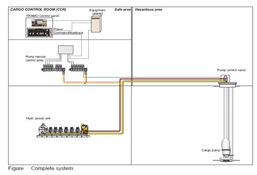
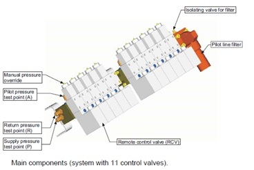
A standard system consists of minimum 2 manifolds. See figure above. Each manifold includes a pilot line filter and service valves (isolating valve on filter inlet, and check valve on manifold outlet). There may be up to 14 valves on each manifold.
2.1 Valve functional description:
A command given by operator (0-10V), corresponds to a required pressure 0-300 bar. The command signal is converted to a solenoid current, driving the proportional solenoid against a spring. At zero command the solenoid force is zero and the spring drives the spool in the fail-safe position, resulting in pilot pressure equal to return pressure.
Increased command gives higher solenoid force and hence pilot pressure. The actual pilot pressure is measured by a pressure tranducer. Its output signal gives both a feedback signal to the operator about actual pressure, and it gives feedback to the valve regulator. If there is a difference between pressure command signal and feedback signal, the internal pressure controller changes the current until difference is minimized (+/- 6 bar accuracy).
The Pump Control valve may be equipped for both local and remote control. It is required that when using the remote control (RCV) the local control valve must be set in maximum position & vice versa. The command signal to the valve is usually set by a control potmeter at Framo Control Panel Before air venting set the command (potmeter) for all RCV on the Framo Control Panel to half position. Start power pack and run at minimum system pressure (approx.70 bar).
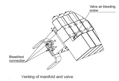
Air bleed main bores in manifold, P and R, by connecting a test hose to P and R bleed test connections. Ref. figure below. Then bleed on connections A on each valve the same way. Finally, air bleed valve internals by opening air venting screw on valve. Slowly open the venting screw about one turn and wait until the oil is free of air bubbles. Then close air venting screw.
2.2 Normal operation from control panel:
The pump is normally operated from Framo Control Panel in cargo control room. The control panel includes one control potmeter and one monitoring indicator for each pump. Pump starts when potmeter for actual pump is pushed forward. Achieved pilot pressure to pump control valve can be read at monitoring indicator (pilot pressure is measured on pressure control manifold).
Note: When pump is in maximum speed control, pilot oil flows from remote control valve to STC
valve, and measured pilot pressure may differ from actual pilot pressure on STC valve, because of pressure drop in pilot line.
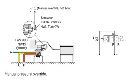
2.3 Manual pressure override:
In case of electrical failure you can mechanically connect the port P to port A, and run the cargo pump by the local control valve. Remember to unload local control valve before changing to manual override. Loosen the lock nut at the end of the valve (see fig. 7), and screw the hexagon socket set screw clockwise.
After manual operation is finished, connect port A to port R by screwing counter-clockwise. DO NOT USE FORCE ON THE SCREW FOR MANUAL OVERRIDE. Fasten the lock nut.
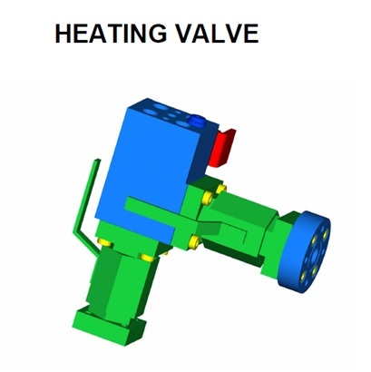
3. Heating Valve.
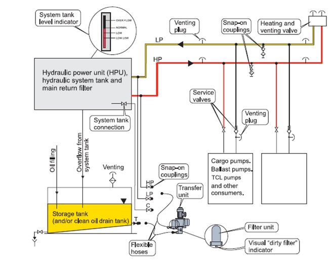
4. Oil filling of hydraulic piping system
If the HPU (Hydraulic Power Unit) is located aft, the ship should preferably have aft trim during oil filling and venting and forward trim if it is located forward. Note! Always fill oil by pumping into the lowest part of the system to avoid mixing with air.
Venting must be done from all the high points in components and pipes, both on pressure- and return side. If deck machinery is connected to the system, these are normally at the highest level.
Avoid oil spill during venting by using a flexible hose with 7 mm inner diameter on the venting Plug, and collect the oil in a suitable bucket.
Use the following filling procedure):
1. Check storage tank oil level and drain off a small quantity of oil for visual check.
2. Close heating and venting valve, and open all venting plugs on the pressure side highest points. 3. Connect hydraulic oil transfer unit for filling from T and into HP (high pressure) line, and start the pump. 4. Vent on all highest points until the pressure side is completely filled with oil, then stop the transfer pump. 5. Open all venting plugs on the return side highest points. 6. Change for filling from T and into LP (low pressure) and start transfer pump.
7. Vent on all highest points including main return filter until the return side is completely filled with oil. Stop transfer pump at normal system tank level.
8. Connect transfer unit for circulation from C to HP. Open heating and venting valve, and start transfer pump. 9. Circulate the oil and vent until the piping system seems to be completely free from air.
10. Stop transfer pump and let the oil settle for at least 12 hours, then restart for circulation and venting. 11. When the system is completely free from air, stop transfer pump, close valves and disconnect flexible hoses.
Note! The valves for oil transfer must always be closed, and flexible hoses disconnected after use.
PILOT LINES AND CONTROL VALVES VENTING
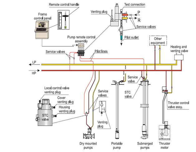
1. Keep the heating and venting valve closed.
2. Close the pressure service valve in front of the pump control valve (STC
valve).
3. Open the STC local control valve completely.
4. Put the remote control handle (on
the panel) in max. position.
5. Open the pressure service valve in front of the pump remote control assy.
6. Start one power pack and set the system pressure to 70-100 bar.
7. Vent the pump remote control assy. through the test connections and the
venting plugs until it is completely filled with oil.
8. Open the service valve on the pilot outlet from pump remote control assy.
9. Open the vent plug on the pump’s return service valve (for venting of the
return side).
10. Vent the STC valve local control valve (must always be open when venting) and the valve cover until the valve and its pilot line is completely filled with oil..


 REQUIREMENTS")