

Q Explain with the aid of sketch, the working principle of IGBT(Insulated Gate Bipolar Transistor) in varying motor speed control
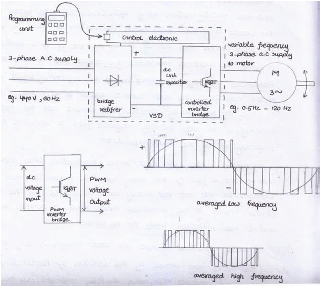
- This type of converter used for induction motor drives, uses transistors as switching devices.
- Unlike thyristors, a transistor turned on and off by a control signal, at a high switching rate (e.g. at 20 kHz in a PWM converter).
- From 440 V A.C supply is rectified and smoothed by the capacitor, voltage about 600 V.
- D.C voltage is chopped into variable-width, but constant level, voltage pulses in the computer controlled inverter section using IGBTs (insulated gate bipolar transistors).
- This process called pulse width modulation or PWM.
- By varying pulse widths and polarity of d.c voltage, an averaged sinusoidal A.C output over a wide range of frequencies typically 0.5 ~ 120Hz.
- Due to smoothing effect of motor inductance, motor currents appear to be nearly sinusoidal in shape.
- By sequentially directing currents into three stator windings, a reversible rotating magnetic field is produced at frequency set by PWM converter.
- Accurate control of shaft torque, acceleration time and resistive braking programmed into VSD.
- VSD closely tuned to connected motor drive to get optimum control
- VSDs can be easily networked to other computer devices
- e.g. programmable logic controllers (PLCs) for overall control of a complex process.
(a) Sketch and describe about IGBT.
(b) Explain about IGBT brick test procedure
(a) IGBT (Insulated Gate Bipolar Transistor)
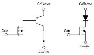
- The Insulated-gate bipolar transistor (IGBT) is a 3-terminal, power semiconductor device.
- It is high efficiency and fast switching, primarily used as an electronic switch.
- IGBTs are used in the various application such as variable frequency drives (VDFs), electric cars, trains, & variable speed refrigerators.
(b) IGBT brick test procedure
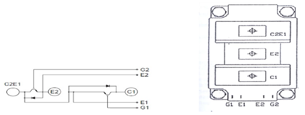
(1) Collector – Emitter junction test
- Short out G1 to E1 and G2 to E2
- With a Multimeter set in ‘Diode-test’ mode, check across the C1-C2E1 junction with the (+) probe on C1 and the (-) probe on C2E1, meter should show “an open circuit”.
- Switch the probes, and then the meter should show “a diode drop” (V-drop across diode).
(2)
- Check across the C2E1-E2 junction, with the (+) probe on C2E1 and the (-) probe on E2, meter shows “an open circuit”.
- Switch the probes, and then the meter shows “a diode drop”
(3) Gate test
- With a 9-V battery, connect the (+) terminal to G1 and the (-) terminal to E1, meter (set in Diode-test) should show “a diode drop” across the C1-C2E1 junction in both directions now.
- Connect the (+) terminal to G2 and the (-) terminal to E2.
- Meter should also show “a diode drop” across the C2E1-E2 junction in both directions.
(4) If the IGBT passed all of the above tests, the IGBT is good.
(a) Make symbols and truth table of the output of the following two input logic gate.
(i) AND (ii) OR (iii) XOR (iv) XNOR
(b) Draw the block diagram of the major components of a common PLC.
(a)
(i) AND Gate
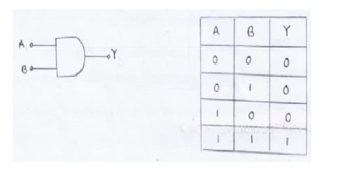
- Have two or more inputs and one output.
- Output is high only when all inputs are high
- In all other cases, output is low.
(ii) OR Gate
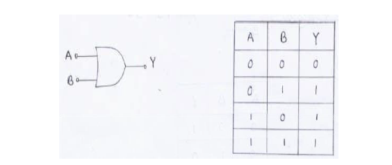
- Have two or more inputs and only one output.
- Output high when both inputs are high (or) any one input high.
(iii) XOR
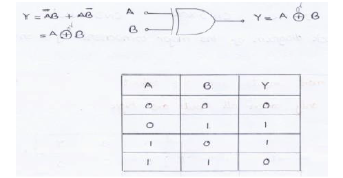
- Output is high only when any one input is high.
(iv) XNOR
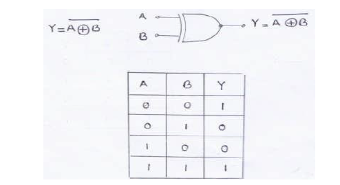
- Inverse of XOR
- Has two inputs and single output
- Output is low if inputs are different.
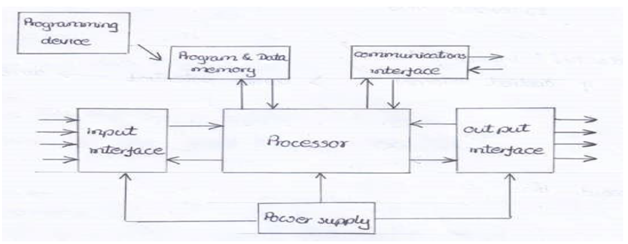
(b) PLC
(a) What is programmable logic controller?
(b) What do you understand the logic gate? Explain with one example how logic gate works.
(c) Describe the advantages of PLC over the electrical relay circuit.
(a) Programmable Logic Controller
- Programmable logic controller (PLC) is special form of microprocessor-based controller
- PLC controllers use programmable memory to store instructions and to implement functions such as logic, sequencing, timing, counting and arithmetic in order to control machine or processes.
- Input devices, e.g. sensors, switches, and output devices in system control e.g. motors, valves, etc. are connected to PLC.
- PLC is digitally operating system designed for use in an industrial environment.
- PLC use to control simple and repetitive tasks and constantly monitors state of system.
(b) The logic gate
- In digital system, such as computer systems are represented by two different voltage levels or two different current levels.
- If more positive of two voltages or currents levels represents a logic ‘1’ and less positive of two levels represent a logic ‘0’, logic system is referred to as positive logic system.
- If more positive of two voltages or currents levels represents a logic ‘0’ and less positive of two levels represent a logic ‘1’, logic system is referred to as negative logic system.
AND Gate
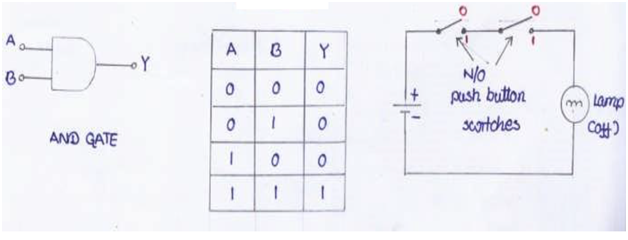
- An AND gate is a logic circuit having two or more inputs and one output.
- Output are high only when all inputs are high.
- Used fire alarm system.
- When smoke and heat or flame detector activate, pump will run.
- If one of detectors activates, pump will not run and alarm sounded only.
(c) Advantages of PLC over the electrical relay circuit
PLCs have several advantages over the electrical relay circuits;
1. The same basic PLC controller can be used with a wide range of control systems.
2. To modify a control system all that is necessary is for an operator to key in a different set of instructions.no need to rewire.
3. PLCs are flexible, reliable, compact and cost effective system which can be used to control a complex system.
4. PLCs are similar to computers but they are optimized for control tasks and designed to use in an industrial environment.
5. PLCs are smaller physical size than hard-wire solutions.
6. Less maintenance
7. Easier and faster to make changes.
8. PLCs have integrated diagnostics and override functions.
9. Diagnostics are centrally available.
10. Applications can be immediately documented
11. Applications can be duplicated faster and less expensively.
12. Rugged and designed to withstand vibrations, temperature, humidity and noise.
13. Have interfacing for inputs and outputs already inside the controller.
14. They are easily programmable and re-programmable.


