

Megger is the most portable insulation tester. It is used to measure very high resistance of the order of Mega ohm.
Types of Megger
This can be separated into mainly two categories:-
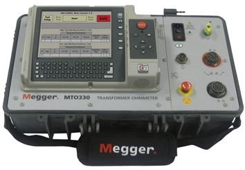
- Electronic Type (Battery Operated)
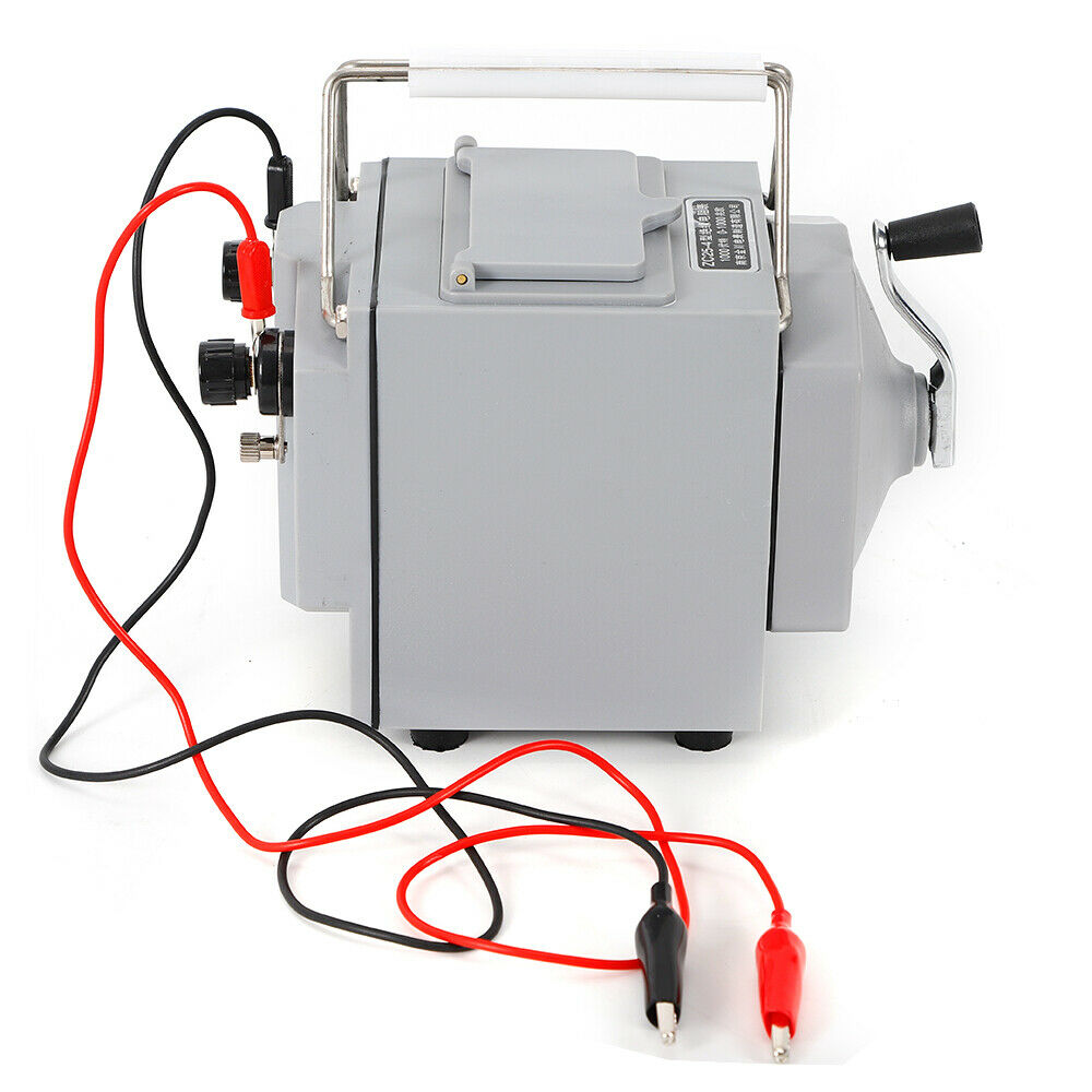
2. Manual Type (Hand Operated)
Principle
This instrument works on the principle of ratio meter/ohm meter. The deflection torque is produced by both the system voltage and the current. Due to interconnection between the magnetic fields produced by the voltage and the current, the deflecting torque is produced. The coils are so positioned that the deflecting torque is proportional to the ratio.
Construction
It consists of:
- A hand driven d.c. generator.
- A moving element which has 2 coils, a deflecting coil (or a current coil) and a controlling coil (or potential coil)
- Calibrated scale in MΩ.
- Pointers and
- Permanent magnet.
The coil are rigidly mounted at sight angles to each other. They are attached to the small hand driven generator. The coils move easily in the air gap of a permanent magnet. To protect the coils under short circuit, a limiting resistor connected in series with the coils.
Operation
Resistance to be measured is linked across the test terminals i.e. connected in series with deflecting coil and across the generator. When currents are supplied to the coils, then they have torque in opposite directions.
If the resistance to be measured is high, no current will flow through the deflecting coil. The controlling coil will set itself perpendicular to the magnetic axis and hence, set the pointer at infinity.
If the resistance which is to be measured is small, a high current flow through the deflecting coil and the resulting torque sets the pointer to zero.
For intermediary values of resistance, depending upon the torque production, the pointer is set at a point between zero and infinity.
The hand driven generator is a permanent magnet type and it is designed to generate from 500 to 2500 volts.
Checking correct operation
Shorten the probes together and switch to MΩ the pointer should indicate approximately ‘0’.
Megger is used to measure insulation resistance and other high resistance values, It is also used for ground continuity and short circuit testing of electrical power system. The chief advantage of the megger over an ohmmeter is its capacity to measure resistance with a high potential or breakdown voltage.
Impedence of insulation is very high. A megger is specifically designed to accurately measure high impedences. An ordinary multimeter is designed to measure lower, more finite impedences. Therefore a megger is more accurate for the application.
Insulation Testing
- A calculation of the insulation resistance gives one of the best guides to the state of health of electrical equipment. The resistance should be measured between circulated conductors and earth, and between conductors.
- A megger type IR tester shoiuld be used to check whether the circuit to be tested is live. Switch the instrument to ‘MΩ’ and connect the probes to pairs of equipment terminals. DO NOT press the button. The meter will now indicate that the circuit is live or not. If the circuit is dead then it is safe to press the test button. make sure that the well grounded earth connection is achieved by connecting the probes to two separate earth points on the equipment frame while testing for low resistance continuity.
- For an IR test on a 3phase machine, measure and log the phase to phase insulation resistance values. Three readings should be calculated as U-V, V-W, W-U.
- calculate and log the phase to earth insulation resistance values. Three readings should be calculated as U-E, V-E, W-E.
- Insulation becomes more leaky at high temperature i.e. IR decreases with increase of temperature so testing while hot shows the realistic IR value at or near, its working temperature.
Continuity Testing
A insulation tester (multimeter) normally also incorporate a low voltage continuity test facility. This is a low resistance instrument for measuring the continuity of conductors. It should be used to measure the low resistance of cables, motor windings, transformer windings, earthing straps etc. procedure is as follows:
- Prove the correct operation of the instrument.
- Isolate and lock off the equipment to be tested.
- Prove the equipment to be dead.
- Switch the instrument to ‘Ω’ or continuity.
- Connect the probes to the circuit.
- Operate the test switch and check the indication on the ‘Ω’ scale. Log all readings.


 REQUIREMENTS")