

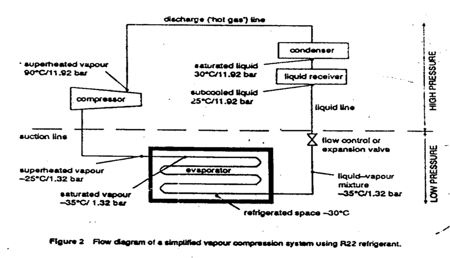
Refrigeration Cycle
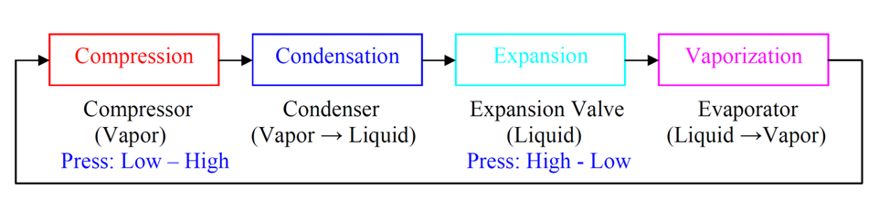
Compression
The function of a compressor is to raise the pressure of a refrigerant vapour, by compressing the vapour. With the function of the compressor, a refrigerant carries heat from low temperature region to high temperature region, while circulating in the closed loop of the refrigeration cycle.
When its volume is reduced by compression, the pressure of a gas becomes high and therefore it is possible to condense easily by cooling water or air of room temperature because this temperature is higher than the refrigerator chamber.
Condensation
The condenser cools the gas discharged from the compressor and turns it into a liquid. The water-cooling system or air-cooling system is available to cool compressed gas.
The cooled and liquefied refrigerant is stored either in the condenser or the liquid receiver.
Expansion
Liquefied refrigerant is passed through an expansion valve, where its pressure is reduced to enable optimum evaporation in the evaporator. The function of the expansion valve is to reduce refrigerant pressure and to control quantity of refrigerant to the evaporator.
Vapourizarion
The liquefied refrigerant is evaporated to vapor state in the evaporator. The low pressure liquefied refrigerant in the evaporator absorbs heat from the surroundings (air being passed through the evaporator) and thus gets evaporated to become dry vapor. Thus, the object of refrigeration is achieved.
DEFINITIONS
Enthalpy- A thermodynamic quantity equal to the total heat content of a system. It is equal to the sum of the internal energy of the system plus the product of pressure and volume.
Specific Enthalpy- Specific Enthalpy is the total energy in a system due to pressure and temperature per unit of mass in that system.
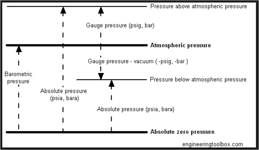
Pressure- Absolute pressure is zero-referenced against a perfect vacuum, so it is equal to gauge pressure plus atmospheric pressure.
Gauge pressure is zero-referenced in terms of ambient air pressure, so it is equal to absolute pressure minus atmospheric pressure.
Latent heat of vaporization- When a material is in liquid state is given energy by some sources, it changes its phase from liquid to vapour; the energy absorbed in this process is called heat of vaporization.
Saturation temperature- The saturation temperature is the temperature for a corresponding saturation pressure at which a liquid boils into its vapour phase.
Saturation pressure- The pressure of a vapour which is in equilibrium with its liquid (as steam with water)
specifically : the maximum pressure possible by water vapour at a given temperature.
Entropy – It is a thermodynamic term which indicate the absence of a system thermal energy for conversion into mechanical work, often interpreted as the degree of disorder or randomness in the system.
MOLLIER DIAGRAM
A p-h diagram (pressure – enthalpy) is a graph with a vertical axis of absolute pressure and a horizontal axis of specific enthalpy. It is an important diagram, used frequently for performance calculation of a refrigerating machine.
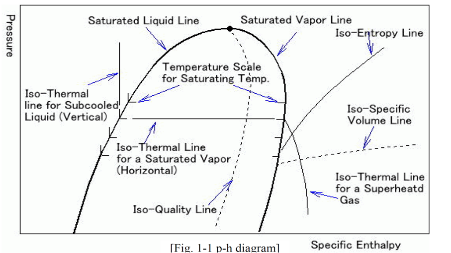
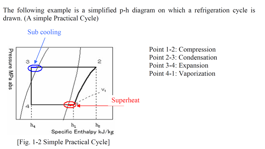
The refrigerant exists as a mixture of vapour and liquid under the Saturated Liquid line and Saturated Vapour line.
To the left of the Saturated Liquid line the refrigerant exists as a liquid.
To the right of the Saturated Vapour line the refrigerant exist as a superheated vapour.
On the diagram, the refrigeration cycle is represented by the line 1-2-3-4.
1-2 is where the gas is compressed resulting in rise in pressure and enthalpy, which equals the energy put into the gas by the compressor, all in the superheat region.
2-3 is where the gas is condensed to a liquid.
3-4 is where the vapour is passed through an expansion valve; the pressure is reduced without any enthalpy change.
4-1 is where the liquid is evaporated completely to a gas and where enthalpy is extracted from surroundings. This is the REFRIGERATION or COOLING effect.
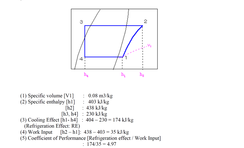
Coefficient of Performance
The coefficient of performance or COP (sometimes CP or CoP) of a heat pump, refrigerator or air conditioning system is a ratio of useful heating or cooling provided to work required. Higher COPs equate to lower operating costs.
For a refrigeration system a COP of 4 indicates that 1 kW of electricity is needed for a evaporator to extract 4 kW of heat.
Refrigerant
A refrigerant is a mixture or substance, normally a fluid, used in a heat pump and refrigeration cycle. In most of the cycles it undergoes phase transitions from a liquid to a gas and back again. Many working fluids has been used for such purposes.
A refrigerant works as a medium to move heat from one place (being cooled) to another place (where this heat is supplied to another medium), while circulating in closed loop of the refrigeration cycle.
- be non-toxic.
- be non-flammable
- have a low boiling point, boil or evaporate easily.
- condense easily.
- not mix with oil since compressor parts are lubricated.
- have a high latent heat capacity to transport energy around the refrigeration system.
- operate at moderate pressures to reduce compressor work and leakage.
- be relatively cheap to produce and store.
Expansion Valve
The thermostatic expansion valve responds to the evaporator temperature and the pressure, and thus maintains a constant superheat at the outlet of the evaporator. There are two kinds of thermostatic expansion valve i.e. internally equalized valve and externally equalized valve. As refrigerant is fed to the evaporator, the liquid boils off into a vapor. By the time the refrigerant gas reaches the end of the evaporator, it is superheated. Feeding more refrigerant to the evaporator will lower the superheat temperature, while feeding less refrigerant to the evaporator will raise the superheat temperature.
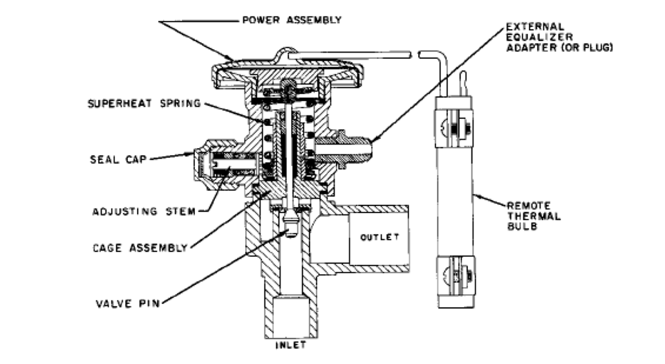
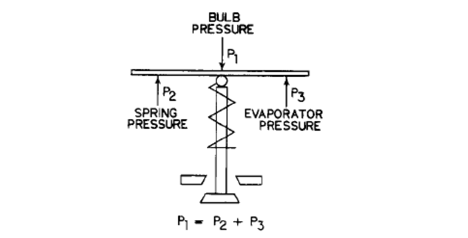
Sensing Bulb & Equalizing
A feeler bulbs partially filled with a volatile liquid, typically the system refrigerant, is clamped to the outlet of the evaporator so that the bulb and the power fluid inside closely assume the evaporator outlet gas temperature. The pressure of power fluid is applied to the top of the valve diaphragm and the evaporator pressure acts on the bottom. A spring applies a force and balances the valve assembly as shown. For the valve to open and feed refrigerant to the evaporator, the bulb pressure must be higher than the evaporator pressure. Since, the bulb pressure responds to the evaporator outlet temperature, this can only occur when the evaporator outlet gas is superheated. The spring is normally adjusted to about 5℃ of superheat in service.
Valves, set for less than this, will not operate properly and may flood back liquid refrigerant to the compressor
An internally equalized valve has a small port, which admits the valve outlet pressure (i.e. the evaporator inlet pressure) to the bottom of the valve diaphragm. Some refrigeration systems have an appreciable pressure drop in the evaporator. Use of an internally equalized valve in such applications will result in unacceptably high superheat at the evaporator outlet. The solution is to use an externally equalized valve, which has a fitting for connecting the evaporator outlet pressure rather than the inlet pressure to the bottom of the valve diaphragm. In general, an externally equalized valve should be used when the evaporator pressure drop is sufficient to change the saturation temperature 1.5℃ in air conditioning systems and 1℃ in refrigeration systems.
The superheat setting of most thermostatic expansion valves is adjustable. Remove the seal cap on the valve and turn the adjusting stem with a screwdriver. Turning the stem to the right increases the spring pressure, reducing refrigerant flow and thus increasing superheat. Turning the stem to the left decreases the spring pressure, increasing refrigerant flow and thus reducing superheat. Two turns of the stem will typically change the superheat about 0.5℃.
Refrigerant Charging
To add refrigerant to an operating system, proceed as follows:
(1) Measure the weight of a refrigerant bottle by scale.
(2) Hook up the refrigerant bottle backward and prepare the charging pipe.
(3) Connect the charging valve and purge air from the charging pipe by refrigerant before flare nuts of charging valve is tightened. Note: The connection point is normally before dryer.
(4) The bottle is put down. It means that the refrigerant is supplied liquid state.
(5) After making sure that each flare nut is tightened satisfactorily, open the charging valve and stop valve of a refrigerant bottle.
(6) Close the stop valve after the receiver for pump down.
(7) Start compressor and charge additional refrigerant
(8) Continue charging until required amount of refrigerant has been charged.
(9) After charging is complete, stop the charging valve and stop valve of a refrigerant bottle.
(10) Disconnect the charging pipe and store a refrigerant bottle.
Removing Refrigerant
If the refrigerating system is charged excessively with a refrigerant, the HP pressure rises, and liquid refrigerant is returned to the compressor, when the expansion valve is not properly adjusted, thus not only the suction line but also the compressor are coated with frost. In such a case, the excess refrigerant must be removed. With all refrigeration system valves in their normal operating positions, proceed as follows:
(1) Shut off liquid supply to evaporators and carry out pump down. Close dryer by-pass valve, open dryer inlet valve and check that dryer outlet valve is closed.
(2) Measure the refrigerant bottle. Place on deck at an angle slightly above horizontal with bottle valves at high end. The position of the bottle should better be lower, if possible, than charging valve.
(3) Connect the stop valve of a refrigerant valve with the charging pipe and purge air.
(4) Open the stop valve of a refrigerant valve and the charge valve. Liquid refrigerant will flow into the refrigerant bottle.
(5) In this time, the bottle outside is cooled by ice and so on. It makes the lower pressure than condenser.
(6) Close the stop valve of a refrigerant valve and the charge valve, when required amount of refrigerant has been removed.
(7) Disconnect the charging pipe and store a refrigerant bottle.
Removing Air
Air and non-condensable gas, if present in the system, are pumped through the system and discharged by the compressor into the condenser. These gases are trapped in the condenser and cause excessive condensing pressures and the HP gas pressure to become abnormally high.
Oil Charging
When adding oil into the compressor, it is important to prevent air and moisture from entering the system.
The supplying procedure is carried out by the following procedures:
(1) Connect the charging pipe of LO into the oil-charging valve and supply new oil into an oil pan for exclusive use for refrigerant oil.
(2) Open the oil-charging valve just a crack and purge air in the charging pipe by gas pressure in the compressor.
(3) After purging air, close the oil-charging valve.
(4) Close the suction valve and open the delivery valve of the compressor and then start it.
(5) After confirming that the vacuum in the compressor reaches about 0.2bar, stop the compressor.
(6) Open the oil-charging valve slowly while checking the oil level and oil is easily supplied into the crankcase of compressor by vacuum.
Oil Removing
Proceed as follows to remove oil from a compressor crankcase:
(1) Connect the charging pipe of LO into the oil-charging valve.
(2) Stop the compressor.
(3) Open the oil-drain valve and remove oil by refrigerant gas pressure in the crankcase.
Leak Detection
1) Mackinly Refrigerant Gas Detector (Halide Torch Gas Detector)
Refrigerant leak detectors contain a halide torch that uses a propane gas flame to detect refrigerants. If halogenated refrigerant vapours are present, the flame changes from blue to a blue-green color. If gas leakage is big, the flame color becomes violet
2) Automatic Gas Detector (Electric type)
This detector is controlled by a microprocessor and can detect CFC, HFC, HCFC and also a mixture refrigerant. Leakage can be known by an indicator lamp, meter or sound.


 REQUIREMENTS")