

Starting air line explosions occur during the start sequence, when the oil, which can accumulate in the air start receivers or on the surface of the start air lines, becomes entrained with high pressure air in the air start manifold & ignited.
The source of the ignition for these explosions can be attributed to one of the following reason:
- A leaking air start valve when the engine is running, the hot gases produced as the fuel burns in the cylinder (at above 1200°C) leak past a valve which has not re-seated correctly. The branch pipe of the air start manifold heats up to red hot. If the engine is stopped & restarted before the pipe has time to cool, any oil vapour in the air can be ignited & an explosion can result if the mixture of oil or air is correct.
- Fuel leaking inside the cylinder when the engine is stopped. When the engine then undergoes a start sequence, & builds up speed, the fuel which has been leaked into the cylinder vaporises & the heat from the compression of the air in the cylinder, as the piston rises, ignites the fuel. When the air start valve opens as the piston comes over the TDC, the pressure inside the cylinder is higher than the air start pressure, & the burning combustion gases pass to the air start manifold, igniting the oil entrained in the air.
- The main cause of the explosions in starting air manifolds of the marine engines is probably the auto ignition of the oil deposited on the inner surface of the manifold, not backfire from cylinders as previously thought. Auto-ignition conditions occur because of the high temperature produced by the rapid inflow of the high-pressure air. This incoming air compresses air downstream of the main starting valve, leading its temperature to reach as high as 400°C which in some cases causes the oil deposits in the manifold to self-ignite leading to an explosion.
To minimise the risk of the explosions, the oil carry over from the compressor should be reduced to minimum. Class regulations require that the air compressor’s air intakes are located in an oil-free atmosphere, & a drain/filter for intercepting oil or water mist is installed between the compressor discharge and air receiver. There must be complete separation of compressor discharge & starting air supply to engines at the receiver which is installed with a drain & a relief valve.
The air start system must be protected with a non return valve at the starting air supply to each engine. This is generally part of the automatic valve which opens when an air start is initiated
In addition to this IACS require that:
- For direct reversing main engines >230 mm bore flame arresters or bursting discs are required for each cylinder fitted between the cylinder start air valve & the manifold.
- For non-reversing & auxiliary engines >230 mm bore a single flame arrester or bursting disc is acceptable fitted at the supply inlet to the starting air manifold.
Although not part of the IACS regulations, a relief valve may be installed to the manifold where flame arrestors are used instead of the bursting discs.
Unsatisfactory practices which have led to explosions in the air start system include:
- Tell tales/drains at each end of the starting air manifold found to have been blanked off with the screwed plugs.
- Failure to drain the starting air receivers & starting air pipes at regular intervals or before manoeuvring.
- Failure to check for the leaking air start valves.
- Failure to maintain starting air valves and systems strictly in accordance with manufacturers recommended practices.
- Failure to maintain fuel valves correctly.
SAFETY DEVICES
Flame Arrestors
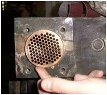
The flame trap is manufactured from the brass or the aluminium alloy which both have a high specific heat capacity. So many holes are bored through the thick circular form to enable the air to pass through it. They are installed in the main air line immediately before the air start valve to restrict the risk of a flame in the cylinder propagating back to the main air start manifold, by dissipating the heat energy in the flame.
Bursting Disks
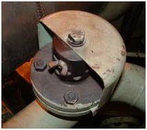
The safety cap consists of a bursting disk enclosed by the perforated cylinder & a perforated cover in order to protect any bystanders, in the event of a burst. The cover is installed with a tell tale, which shows if the bursting disc has been damaged. If the bursting disc of the safety cap is damaged due to the excessive pressure in the starting air line, overhaul or replace the starting valve which caused the burst, & mount a new disk
If a new disk is not available, or cannot be fitted immediately, then the cover can be turned in relation to the perforated cylinder, in order to reduce the leakage of the starting air.
Relief Valve
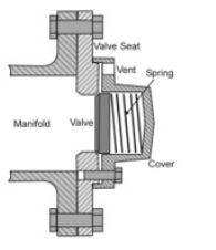
The figure shows a relief valve as installed to the air start manifold of the Sulzer RTA 2 stroke engines. Its purpose is to relieve excess pressure in the air start manifold. It consists of the spring loaded valve disk which locates on a mating seat which is bolted to the end of the air start manifold. When the force exerted on the disk due to the excessive pressure is greater than the spring force holding the valve closed, the valve will open.


 REQUIREMENTS")