

For the large bore diesel engine, a combined cycle plant setup has so far been based on a standard design and, thereby, also standard performance of the diesel engine, leaving waste heat recovery (WHR) to boiler and steam turbine producers. Such a setup has of course contributed to improvement of the total efficiency of the combined plant, but not necessarily secured the best possible utilization of fuel.
However, the overall task could be redefined. Instead of searching the optimal solution for the individual machines (engine, turbocharger, power turbine, boiler and steam turbine), a combined optimum for the entire process could be the target. The main success criterion is optimal efficiency (i.e. reduction of CO2) of the system as a whole, however, with consideration to such side effects as emissions from the system.
Simple system calculations for two-stroke engine plants clearly indicate that a reduction of the scavenge air amount, and thereby an increase of the exhaust gas temperature level, which leads to reduced efficiency of the diesel engine itself, at the same time creates a remarkable potential for increased power output on both power turbines and steam turbines. The above mentioned potential compensates the reduction of diesel engine efficiency with surplus.
Accordingly, the objectives would be as follows:
- To encircle, by calculation and test, the level of reduced air flow through the engine at which thermodynamic parameters (performance) and the heat load on the combustion components, i.e. piston, exhaust valve, liner and cover, are not jeopardizing the reliability of the diesel engine.
- To develop the principles and investigate, by calculations, different variants of combined systems based on the calculation results and engine tests.
The variants of combined systems consist of the engine as a core element, boilers, power turbine (TCS) and steam turbine – all called Thermo Efficiency Systems (TES). Also variants of TES systems combined with Scavenge Air Moisturising (SAM) or Exhaust Gas Recirculation (EGR) systems are evaluated, as such systems will probably be applied on future engines due to expected new NOx emission regulations, as well as for economical reasons of the engine production.
Engine test
To confirm the potential, a reduced-air-flow test has been made on the several engine types in the bore range S50ME-C to K98MC. The following will briefly report on the results obtained from the K98MC engine tests.
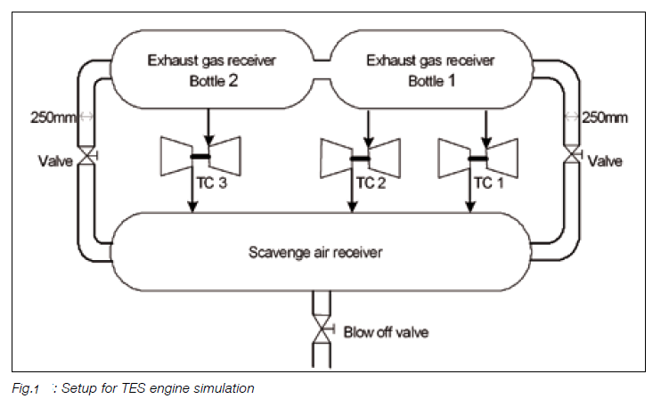
The simulation was made by introducing a cylinder bypass installed from the scavenge air receiver to the exhaust receiver and controlled by an adjustable valve and a scavenge receiver blow off valve, see Fig. 1. Turbocharging efficiencies of ~60% to ~62% were simulated by observing the turbine inlet temperatures on the turbochargers and adjusting the bypass valve. The temperatures observed were then compared with calculated simulations.
SFOC and emissions
A comparison of measured SFOC and NOx is given in Fig. 2.
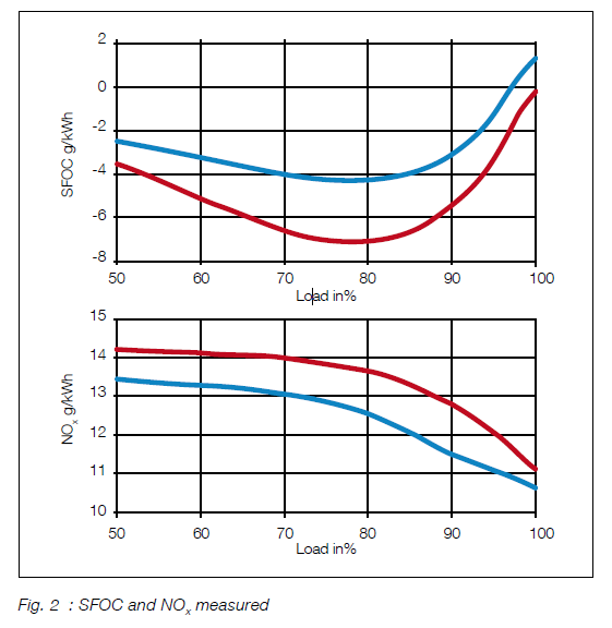
The SFOC increases when the bypass is opened. This is fully as expected and pre-calculated, and is caused by the lower purity in the cylinder caused by the reduced air flow. However, NOx is slightly reduced, which is not completely in accordance with expectations and calculations, but of course represents a potential for reduction of SFOC by fuel system optimizations.
Combustion chamber temperatures
The combustion chamber temperatures for 100% engine load are shown in Fig. 3.
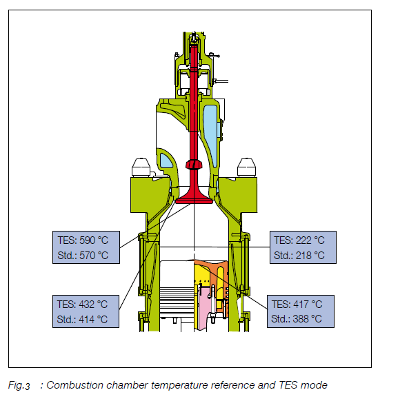
The result from the TES simulation test clearly confirms the pre-calculations. The result also confirms that TES applications can be introduced in service, without hesitation, when combined with the use of HIP-compound slide type fuel valves, and pistons with Inconel cladding and cooling insert.
Traditional application available for commercial application
The TES engine application can be utilized in a traditional TES system with a significant benefit in overall efficiency of the vessel, as illustrated in Fig. 4.
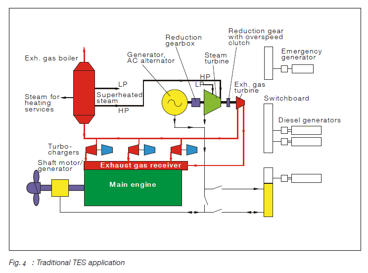
The traditional TES application offers an improvement of the total plant efficiency of approx. 5%, corresponding to approx. 7,000 kW electric power production on the 12K98MC/MC-C/ME/ME-C engines with approx. 73,000 kW shaft power.
Alternative application possibilities
The possibilities for TES engine application also allow for different options of other boiler TCS system configurations, as well as combining these TES applications with SAM and EGR applications.
TES applications
In all the investigated applications, the operating conditions have been equal to the standard TES application for the applications without SAM or EGR and corresponding to expected normal operating conditions for engines with SAM or EGR systems, see Fig. 5.
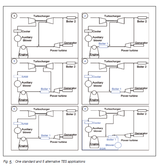
System 1 is the traditional TES system and is used as reference in the following.
In System 2, the boiler has been divided into a low-temperature section after the turbocharger, and a high-temperature section before the turbocharger and power turbine. The benefit of this application is the possibility to increase the steam superheating temperature from approx. 280ºC to approx. 440ºC, increasing the steam turbine efficiency significantly. The disadvantage is a reduced TCS power turbine output due to reduced inlet temperature and reduced gas flow rate.
Combining System 2 with SAM, results in System 3, also shown in Fig. 5. The SAM system in 3 increases the potential bypass flow to the power turbine and, accordingly, increases the power turbine power. The advantages and disadvantages of having both a low temperature and a high-temperature boiler are the same as for System 1.
Systems 4 and 5 correspond to Systems 2 and 3, with the only difference that the high-temperature boiler is moved from the main exhaust gas stream to the bypass exhaust gas stream. By moving the high-temperature boiler from main stream to bypass stream, the bypass mass flow and the heat balance of the turbocharger are unaffected by the high-temperature boiler. The advantage of this system is that the power turbine is reduced only due to lower inlet temperatures. The disadvantage is that the possible power extraction in the high temperature boiler is very limited.
Fig. 5 illustrates five alternative system applications, which have been investigated by calculations only. The calculations were performed in cooperation with Aalborg Industries for the boiler calculations and with Peter Brotherhood Ltd. for the steam turbine calculations.
In this last set up in Fig. 5 (System 5), the high and low-temperature boilers are combined with an EGR system. The advantages of this system are that the power turbine is reduced only due to lower inlet temperatures and that the gas flows through the high temperature boiler are relatively high, because the EGR flow also goes through the boiler.
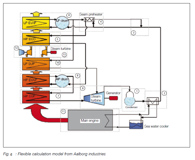
Calculation results
In order to calculate the possible impact of the different set-ups, Aalborg Industries has made the calculation model shown in Fig. 6, giving extended possibilities for building all kinds of systems.
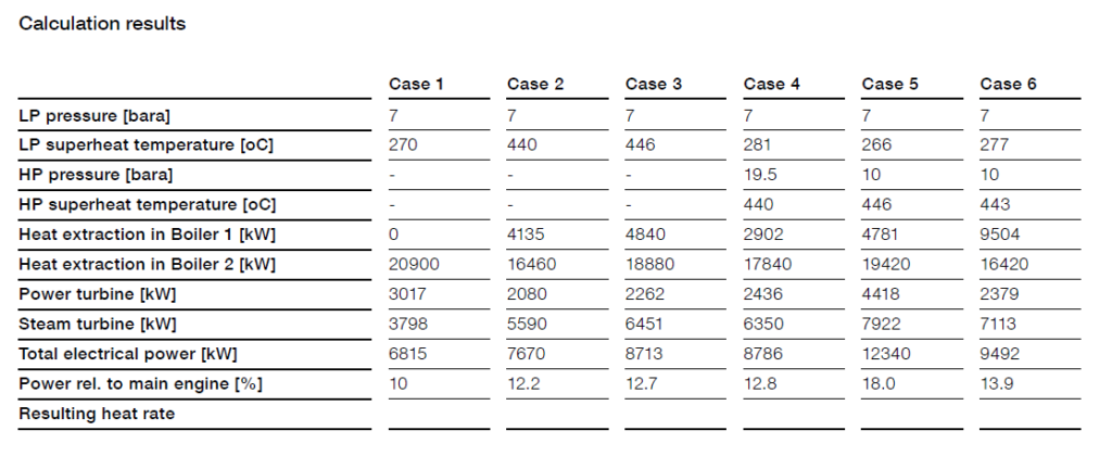
Summation of results
A comparison of the results of the six cases reveals the optimum case.
Table below clearly shows that case 5 gives the best result, in terms of both electrical power output and efficiency. It is not a coincidence that the case with the highest power turbine output has the highest electrical efficiency.
Existing Engines Converted to Tier I
At the IMO MEPC 57 meeting it was decided that the NOx control of existing engines is to be regulated. The regulation will concern engines with a cylinder volume larger than or equal to 90 litres and a power of 5,000 kW, or larger, installed on ships built from 1 January 1990 to 31 December 1999. This requires a retrofit kit for those engines, or an approved method of changing and showing compliance with IMO Tier I.
The kit for retrofitting the MC/MC-C engines from that period is available from MAN Diesel as well as the assistance to make the necessary procedures to be in compliance. The kit contains injection valves designed for the IMO Tier I compliance. PrimeServ Denmark can be contacted for more information.


 REQUIREMENTS")