

Q. Explain the following modern terms related to turbocharging:
A. Pulse converter system
B. Sequential turbo charging
C. Two stage turbocharging
D. Variable geometry turbochargers
Answer:-
A. PULSE CONVERTER SYSTEM:-
- Pulse charging system due to long interval of the air inlet & partial loss of air inlet (multi inlet turbine) which lead a low efficiency of the turbine, in order to enhance the performance of the engine, pulse converting charging system is invented.
- Pulse converting system tries to keep the merits of the pulse system which is its high available energy & the unsteady flow at the exhaust, meanwhile steady & effective flow condition can be obtained for the turbine.
- A real simple pulse converting system used for four cylinder engine is shown in the figure below
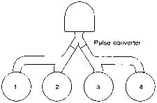
- It uses traditional pulse manifold, using a designed connecting piece to connect the manifold which has two branches to a single turbine.
- Through 4 cylinders connecting to an inlet of the turbine, it totally avoids the interval of the air inlet among exhaust pipes.
- Comparing to the constant pressure system though inlet of the turbine are different it avoids the situation of the pulse system operating in the low efficiency.
- The design of the connecting piece makes the least transfer of the pressure pulse from one pipe of the exhaust pipe to the another, so it prevents that a cylinder’s exhaust pipe breaks another cylinder scavenging process.
- This type of the pulse converter are mostly utilized on medium speed engine especially 4 cylinder, 8 cylinder & 16 cylinder. If engine has cylinder we should use two pulse converter, each pulse converter converting an inlet of the turbine.
B. SEQUENTIAL TURBOCHARGING:-
- The sequential turbocharging system consists of 2 or more turbochargers in parallel, & these turbochargers are put into or out of operation in terms of the diesel engine operation points.
- This system can enhance the turbochargers matching with the engine, so the efficiency of the turbocharger & boost pressure are both enhanced.
- It refers to a setup in which the motor uses one turbocharger for the lower engine speeds, & a second or both turbochargers at the higher engine speeds.
- During low to mid engine speeds, when available spent exhaust energy is minimum, only one relatively small turbocharger is active. During this time, all of the engine’s exhaust energy is transferred to the primary turbocharger only, providing the small turbo’s benefits of a lower boost threshold, minimum turbo lag, & increased power output at the low engine speeds.
- As the rpm increases, the secondary turbocharger is relatively activated in order to prespool before its full utilization. Once the preset engine speed or boost pressure is achieved, valves controlling the compressor & turbine flow through the secondary turbocharger are opened fully.
- In this way a full twin turbocharger installation provides the benefits related with a large turbo, including maximum power output, without the disadvantage of the increased turbo lag.
- Sequential turbocharging system is an effective measure to enhance the fuel economy performance & the transient responsive performance & to reduce the smoke emission at the low speed.
C. VARIABLE GEOMETRY TURBOCHARGER:
- A Variable Turbine Geometry turbocharger also called as a variable geometry turbocharger (VGT), or a Variable Nozzle Turbine (VNT). A turbocharger fitted with Variable Turbine Geometry has movable vanes which can direct exhaust flow onto turbine blades. The vane angles are modified via an actuator. The angle of the vanes changes throughout the engine RPM range to optimize turbine behavior.
- Variable geometry turbochargers are family of the turbochargers, generally designed to permit the effective aspect ratio (A/R) of the turbo to be modified as the conditions change.
- This is performed because the optimum aspect ratio at the low engine speeds is very different from that at high engine speeds. If the aspect ratio is very large, the turbo will fail to create boost at the low speeds; if the aspect ratio is very small, the turbo will choke the engine at the high speeds, leading to high exhaust manifold pressures, high pumping losses, & ultimately lower power output.
- At the low rpm: The vanes are partially closed, decreasing the area hence accelerating the exhaust gas towards the turbine. The exhaust flow hits the turbine blades at the right angle. Both makes the turbine spin faster.
- At the high rpm: At high rpm the exhaust flow is strong enough. The vanes are fully opened to utilize high exhaust flow. This also release the exhaust pressure in the turbocharger, saving the need of the waste gate.
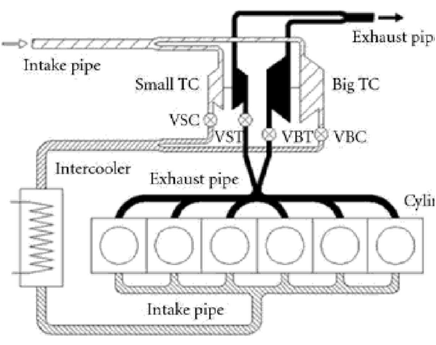
D. TWO STAGE CHARGE TURBOCHARGING:
- Two stage turbocharging system consists of different sized turbochargers that are used in sequence, but both operate constantly. The first turbocharger boosts the pressure as much as possible. Subsequent turbocharger take the charge from the previous stage & compresses it further.
- This type of turbo charging is essential for the engines requiring high degree of supercharging.
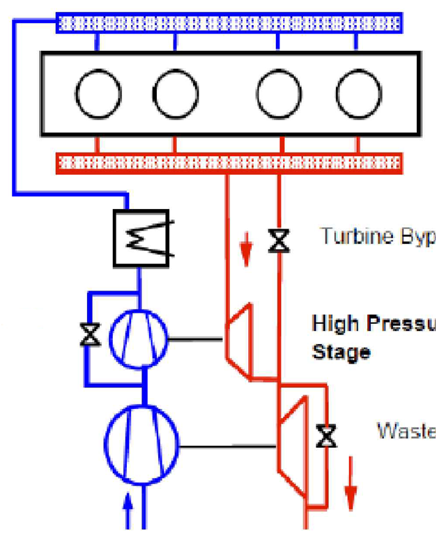
- The exhaust mass flow coming from the cylinder flows into the exhaust manifold first. Here it expand the entire exhaust mass flow by utilizing the high pressure turbine (HP) or to redirecting some of the mass flow through a bypass to low pressure turbine (LP). The entire exhaust mass flow is then used again by the low pressure turbine (LP).
- The entire fresh air flow is first compressed by low pressure stage. In the high pressure stage, it is compressed further & then the charging air is cooled. Due to the pre-compression process, the relatively small HP compressor can reach a high pressure level so that it can force the required amount of air to flow through the system.
- At the low engine speeds, i.e. when the exhaust mass flow rate is low, the bypass remains completely closed & the complete exhaust mass flow is swell by the HP turbine. This leads to very quick & high boost pressure rise. As the engine speed increases, the job of the expansion is continuously shifted to the LP turbine by increasing the cross-sectional area of the bypass accordingly.

 REQUIREMENTS")
