

SYNCHRONIZING AND
PARALLELING OPERATION OF ALTERNATORS
Main
generator units(steam turbine, diesel driven & shaft driven) have to be run
in parallel to share a total load that surpass the capacity of a single machine
specially when discharging cargo, loading cargo, tank cleaning and manoeuvring.
Changeover of main & standby generator units need a brief parallel running
period to attain a smooth transition without a blackout situation.
For the purpose of simplicity & security, it is generally not possible or advisable to run a main generator in parallel with either the emergency generator or the shore supply. Circuit breaker interlocks are fitted to prevent it. Parallel running is achieved in two stages –
synchronising & load sharing. Both can be done automatically but manual control is still in common use & is normally provided anyway as the back-up to the auto control mode. The generator already on the bus bars is called the running machine & the generator to be brought into service is the incoming machine. In order to parallel the incomer smoothly, it must be synchronized with the running generator (or the bus bars); the following conditions are essential:
1. Same voltage
2. Same frequency
3. Same phase sequence
Practically, one may find it difficult to control the speed of the incoming machine so that the pointer of the synchroscope is stationary at 12 O’clock. Such a situation is not essential & a more practical proposition is to have the pointer rotating slowly in the ‘Fast’ direction & to close the paralleling switch at about 11 O’clock. Due to the time lag of the operating mechanism & human response, actual synchronizing will thus take place closer to the 12 O’clock position, & the machine, running faster will be slowed down marginally while taking a small proportion of the load.
If the incoming generator is synchronized when it is running slow, it would slow down further & draw a motoring current, which will actuate its reverse-power relay & trip the circuit-breaker of the machine already on the bus bars due to overloading. If the frequencies are not almost equal at the time of synchronizing, large power transients will occur till they stabilize at the common frequency.
The probable consequences of attempting to close the incomer’s breaker when the generators are not in synchronism are that at the instant of closing the breaker, the voltage phase difference leads to a large circulating current between the machines; this results in a large magnetic force to ‘pull’ the generators into synchronism. This means rapid acceleration of one rotor & deceleration of the other.
The large forces may physically damage the generators & their prime movers, which may include deformation of the stator windings, movement between the stator core & frame, failure of the rotor diodes in brushless machines, twisted rotor shafts, localised crushing of shaft-end keyways and broken couplings. The large circulating current may also trip each generator breaker. Severe vibration of it also a symptom of loss of synchronism. This will be accompanied by flashover at the slip rings in the case of alternators that have a rotating armature. The ultimate result is a blackout, danger and embarrassment!.
The ship’s Power Management System (PMS) has two operating modes: Manual and Automatic. When manual control is selected, the PMS has no control over the generating sets; the generators and their prime movers can be operated locally and also at the main switchboard. For example, the diesel generator local control mode is selected by means of the Local / Remote switch. When the system is set to automatic, the PMS controls the operation of the main switchboard and the three generators.
In order to fulfill the requirements for Unmanned Machinery Space (UMS) operation, the system controls the following features:
1. Automatic blackout start of the standby generator
2. Automatic synchronizing
3. Automatic frequency control
4. Automatic load sharing
5. Preferential tripping of loads
6. Sequential restart of essential consumers
7. Automatic generator start and connection in response to a heavy consumer start request
8. Automatic generator start/shutdown in response to high/low load conditions
9. Pre-selection of the standby generator priority is achieved by operation of the standby generator selection switch on the synchronizing panel.
Manual Synchronizing
The governor control switch of the alternator is moved to the “raise” position; this action will raise the no-load speed setting of the governor. The incomer must be brought up to an appropriate speed to obtain approximately the same frequency or within 0.2% of the bus-bar frequency to achieve smooth synchronizing. The incoming generator’s voltage is now trimmed’ so as to be equal to within 5% of the bus bar voltage. This may not be possible if the load is fluctuating. Fine tuning of the speed can now be observed on the synchroscope or synchronizing lamps, the incomer being adjusted so that the synchroscope pointer rotates slowly (in the “fast” direction) at about 4 to 5 seconds per revolution, counter-clockwise or in clockwise.
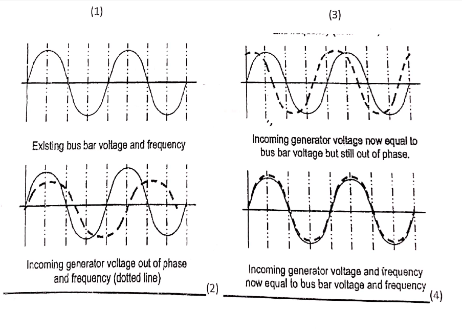
In the case of synchronizing lamps, the lamps brilliancy would also appear to rotate clockwise. This ensures that the incoming machine is slightly fast and it will immediately assume load. Figure below depicts the four basic stages in synchronizing. The circuit breaker should be made as the pointer approaches ’12 O’clock’. Making the breaker between ‘5 to and 5 past the ’12 O’clock’ position of the synchroscope is satisfactory as long as the pointer’s rotation is fairly slow. It is normal to synchronize with the incoming machine slightly fast. This prevents the incoming machine’s reverse power trip protection relay from operating.
The indication available to show the optimum synchronized condition is that the incoming generator ammeter will display a slight ‘kick’ when correctly synchronized. A synchroscope is usually short-time rated (i.e., 15 to 20 minutes) – do not forget to switch it off after synchronizing is complete. If the synchroscope is malfunctioning, then the frequency meter should be used to monitor the incoming alternator’s frequency.

 REQUIREMENTS")
