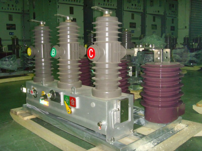
Vacuum switchgear follows the principle that it is virtually impossible for electrical current to flow in a vacuum. Therefore, the main contacts disconnected inside the vacuum bottle. The typical contact material consists of a tungsten matrix impregnated with the copper & antimony alloy to provide the low melting point material to assure continuation of the arc till nearly current zero. The early designs of the vacuum breakers displayed the phenomenon of current chopping i.e. switching off the current at the point on the cycle other than current zero. This sudden collapse of the current produced extremely high voltage spikes & surges into the system, causing failure of the equipment. Another phenomenon was prestrike at switch on. Due to their superior rate of the dielectric recovery, a characteristic of all vacuum switches was the production of the train of pulses during the closing operation. But, of modest magnitude, the high rate of rise of voltage in pre strike transients can, under certain case, generate high insulation stresses in the motor line end coils.
Subsequent developments done to reduce these shortcomings by the use of softer contact materials, in order to keep metal vapour in the arc plasma so that current continues to flow till point zero. Unfortunately, this led to many cases of contacts welding on closing. Restrike transients generated under conditions of stalled motor switch-off were also a problem in vacuum contactors. When switching off the stalled induction motor, or one rotating at only a fraction of synchronous speed, there is little or no machine back emf, & the high voltage appears across the gap of the contactor quickly after extinction. If at this point in time the gap is very small, there is a change that the gap will break down & commence a re-strike transient, puncturing the motor‘s insulation.
Modern designs have all but beat these problems. In vacuum contactors higher working speeds coupled with the switch contact material have chosen to assure high gap breakdown strength, generate significantly shorter trains of pulses. In the vacuum circuit breakers, working speeds are also much higher which, together with the contact materials that assure high dielectric strength at the small gap, have assured that pre strike transients have discontinued to become a significant phenomenon. But, by nature of their design, vacuum switchgear do cause higher voltage peaks when breaking high currents, as compared to the other types of switchgear. With the use of special surge arrestors, e.g. ZORCs and wave-slowing capacitors, the transient over voltages can be prevented from damaging the motor‘s insulation.
Types of closing mechanisms
Hand operated
A cheap version but is losing popularity as the operating speed depends entirely on the operator‘s dexterity. Additionally it is only used at ratings of 150 MVA and less, and up to a maximum of 11 kV.
Hand operated and spring assisted
Hand actuator presses a cam-spring arrangement over top dead center(>90°). The spring is under compression &, once past T.D.C, completes the cycle to 180° & closes the breaker.
Quick make
A variance on the device explained in version (2) above. A spring is compressed & latched by a hand operated system. The spring is then released by the operation of the latch to operate mechanism.
Motor wound spring
Versions (2) and (3) above can have a motor replacing the manual function as explained. Motor-driven systems have gearboxes, & are used for larger systems (high MVA ratings).
Solenoid
Versions (2) and (3) above can have a solenoid replacing the manual function as described; this is more common on the smaller ranges of switchgear.
Pneumatic
Used at 69 kV and above. Convenient, but a supply of dry air is required.
Hydraulic
Hydraulic pressure is progressively being used on the modern circuit breakers.
Internal arc proofing
Internal arc proofing refers to the certified capability of the switchgear to withstand an internal short circuit, typically a busbar fault, for a specified period of time without causing injury to persons standing directly in front of the switchgear panel. Internal arc proofing need to be certified by an authorized testing authority, and will state a current and time rating, e.g. 25 kA, 1 s. The following will typically be features of an internal arc proof panel for 200 ms:
- Mild steel of at least 3 mm thickness for panel construction
- Secured, bolted front doors. The door to the CB enclosure cannot be opened while the CB is racked in.
- CB needs to be racked out with the door closed
- No easy access to busbar chambers, only via bolted covers
- Arc energy will be directed to the top of the panel away from the front doors and blown out‘ at the top via false covers. It is theoretically safe to stand in front of a panel that is being faulted. Because the internal arc proofing is short time rated, bus zone protection is required to reduce the fault clearing time.
Examples of bus zone protection include:
- High- and low-impedance differential protection schemes (operates in less than 10 ms)
- Busbar blocking schemes (operates in 100 ms or more)
- Arc detection schemes (operates in less than 20 ms).


