

(a) Explain about BJT (Bipolar Junction Transistor),Uni-junction transistor.
(b) Describe about NPN and PNP transistor with sketch.
(c) Describe about Thyristor,GTO(gate turn off thyristor)
(d) Describe about MOSFET operation, Snubber circuit.
(a) BJT (Bipolar Junction Transistor)
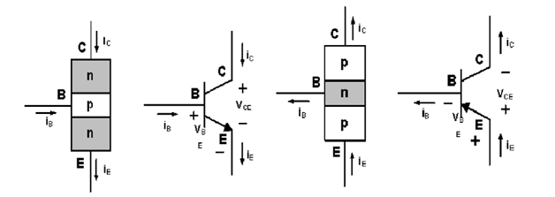
- Three terminal device, fabricated with three separately doped regions.
- Two different types- NPN BJT, PNP BJT
- NPN device has one (p) region between two (n) regions.
- PNP device has one (n) region between two (p) regions.
Uni-junction transistor
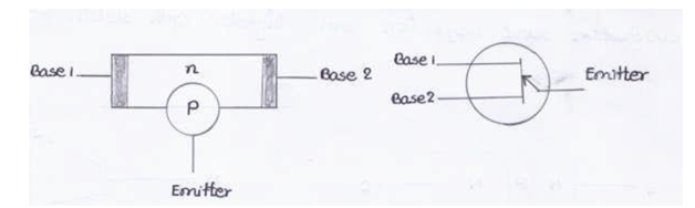
- 3 terminals semiconductor switching device, 3 terminals and 1 junction.
- Single emitter lead and two base lead.
- Consist of a bar of lightly dropped high resistivity semiconductor n type,
- opposite polarity of lightly dropped low resistivity material locate near center of bar.
- Ohmic contacts from each of bar base 1 and 2 and to emitter.
(b) NPN transistor
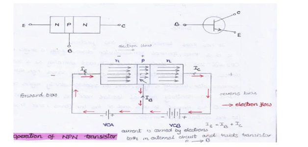
- Forward bias to emitter-base junction and reverse to collector-base junction.
- Forward bias causes electrons in n-type emitter to flow towards base, constitutes emitter current IE.
- Electrons flow through the p-type base, combine with holes.
- Base is lightly doped and very thin.
- only a few electrons (less than 5%) combine with holes, constitute base current IB.
- Remainder (more than 95%) cross over into collector region, constitute collector current IC.
- Entire emitter current flows in the collector circuit.
- Emitter current is the sum of collector and base current. IE = IC + IB. (b)
PNP transistor
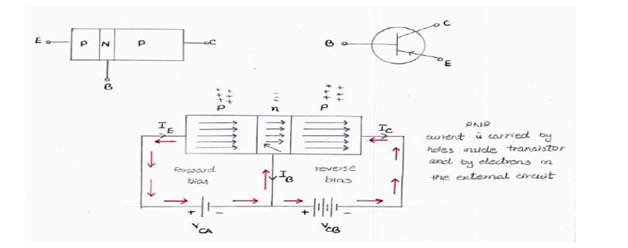
- Forward bias causes holes in p-type emitter to flow towards the base. constitutes emitter current IE.
- Holes cross into n-type base, combine with electrons.
- Base is lightly doped and very thin.
- Only a few holes (less than 5 %) combine with electrons.
- Remainder (more than 95 %) across into collector region to constitute collector current IC.
- Entire emitter current flow in the collector circuit.
(c) Thyristor
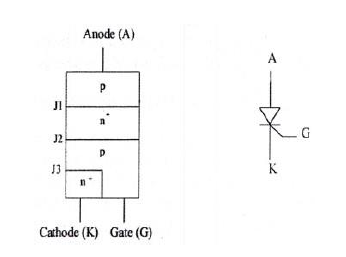
- Solid state semiconductor device. Have 3 leads, 4 layer.
- Thyristors do not amplify fluctuating signals like transistors., Control current either on or off.
- A small current at one lead allow a much larger current to flow through other two leads.
- Two families of thyristor, silicon controlled rectifiers (SCRs) and TRIACs.
- SCRs switch is for direct current and TRIACs switch is for alternating current.
GTO (Gate Turn Off Thyristor)
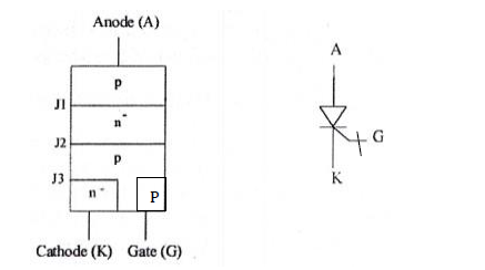
- Power semiconductor switching device, 4-layered PNPN.
- Similar to SCRs, gate can turn the GTO on and off.
- Turned on by a positive gate current and turned off by a negative gate current.
- Reverse gate current amplitude is dependent on anode current turned off.
- No need for an external commutation circuit to turn it off.
(d) MOSFET Operation
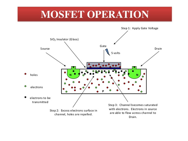
- Unlike junction FET, N type or P type.
- Gate of MOSFET has no electrical contact with source and drain.
- A glass like layer of silicon diode(an insulator) separator gate metal contact from rest of transistor
Snubber Circuit
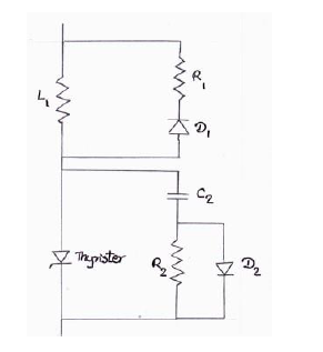
- Essential for diodes used in switching circuits.
- During reverse recovery process, diode can save from overvoltage spikes which arise.
- A very common snubber circuit, power diode consists capacitor and resistor connected in parallel with diode.
- When revere recovery current decrease, capacitor by virtue try to retain voltage across it, which is approximately voltage across diode.
- Resistor help to dissipate some of energy storage in conductor.
(a) Describe briefly about Diode.
(b) Describe about Silicon Control Rectifier.
(c) Explain about rectification with sketch.
(a) Diode
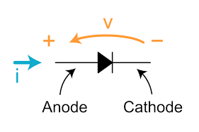
- Diode is an electronic device, current flow in only one direction.
- Used as a rectifier because electrons can flow in only one direction, from cathode to anode.
- Most commonly used in electronic circuits are semiconductor diodes.
(b) Silicon Control Rectifier
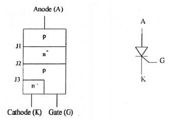
- 4-layered 3terminal solid state device that controls current flow.
- A small current at one lead will allow a much larger current to flow through the other two leads;
- Controlled is either on or off.
- SCRs are mainly used controlling of high power, possibly coupled with high voltage, is demanded.
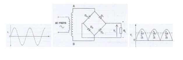
(c) Rectification
- A rectifier is an electrical device that converts alternating current (AC), which periodically reverses direction, to direct current (DC), in only one direction. The process is known as rectification.
- The rectifier circuits can be half-wave or full-wave using with Step down transformer and semiconductor diodes.
(a) What is the purpose of fitting Automatic Voltage Regulation on an auxiliary engine?
(b) Describe how an automatic voltage regulator monitors output voltage and controls the excitation system for ac generator.
(a) Reason for AVR
- Starting of Large induction motor (low pf of 0.3-0.4 lagging) cause load current surge (6-8 times normal)
- Large voltage drop in generator winding, terminal voltage reduce at load.
- Effect is voltage drip, similarly stopping of large motors produce over voltage on bus bar.
- Real need for AVR, sudden connection of extra load and restore voltage quickly without voltage hunting.
(b) Automatic voltage Regulator
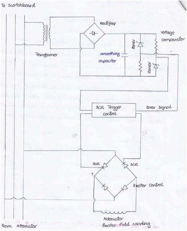
- At voltage sensing unit, generator output transformed, rectified and smoothed to give DC signal.
- DC signal compare with set value produce by electronic circuit of Zener diodes and resistors.
- Output error signal amplified, use to control firing angle of thyristor through triggering circuit.
- AC exciter field coil supplied with regulated DC from SCR output.
- AC exciter rotor output feeds into bridge rectifier.
Q Explain why low voltage protection is provided in an AC system? Briefly describe how this protection is affected?
Undervoltage protection (Low voltage protection)
- Under-voltage protection is electromagnetic or electronic, provide back-up protection to short-circuit protection
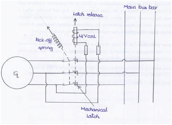
- An under-voltage release mechanism (UVR) fitted, to all generator breakers and some main feeder circuit-breakers.
- Its main function is to trip the breaker, when voltage dip (around 50%) occurs.
- By releasing mechanical latch (which keeps the contacts closed), to trigger trip mechanism, that opens breaker main contacts.
- When generator voltage is very low or absent, U/V release on generator circuit breaker prevents if closed
- Example, during generator paralleling procedures, wrong to close circuit breaker
- Dead generator equivalent of short circuit fault, on bus-bar & cause black out
- Undervoltage relay prevents dead generator circuit breaker from closed.
- Undervoltage protection require for motor starters.
- When supply voltage is lost or reduce, starter contactor normally provides this protection
- When supply voltage restores, starter circuit not allow motor to restart, except when special automatic restarting provide
- during transient voltage dips (typically 15%) caused by large motor starting currents, generator UVR is usually off-delayed (time delay) to prevent tripping
- roduce DC current for alternator field winding to control output voltage.

 REQUIREMENTS")
