

Survey of MSB
- Proper cleaning to be carried internally as well as externally normally carried out when board is completely dead (all generator stopped and prime mover locked off). Inspect for dirt and dust (electro clean and vacuum cleaner.
- All main bus bar and auxiliary connections to be checked for proper tightness.
- Bus bar supports will be checked for surface cracking and damage to insulating material.
- Proper contacts to ensure no ingress of moisture.
- Feeder isolation and fuse holders contacts should be checked for any mechanical damage due to overheating or arcing at the contacts.
- Reverse power relay and preferential trip setting.
- Check dead front If not able to touch for more than 3 sec then problem switchboard.
- Check condition of fuses damaged fuses to be replaced.
- Only approved rubber mat to be used.
- Check indication lamps for working should be in working condition.
- Check safety interlocks.
- Check overheating of bus bars and should be rectified as soon as possible.
- Lubricate mechanisms, contacts and other moving parts.
MSB Safeties
- Minimum 3mm rubber mat (approved and certified) in front as well as back of switchboard.
- Dead front-end switchboard.
- Insulated door handles (Ebonite)
- Panel doors are also earthed.
- Can’t open door, if breaker is closed.
- No pipeline to pass in vicinity.
- Minimum 1m free air surrounding switchboard.
- Short circuit protection (ACB gen.)
- Preferential trip circuit breaker (110%, 115%)
- Reverse power trip circuit breaker (ACB, Gen)
- UV/OV trip circuit breaker (ACB, Gen – 50%)
- OF/UF trip circuit breaker (ACB, Gen)
- Single phasing alarm.
- Over speed trip/relay (ACB, Gen)
- Over Current trip/relay (ACB, Gen)
- Over load trip (ACB, Gen)
- No voltage trip (ACB)
- Fuses, meter, synchronoscope
- Earth fault indication.
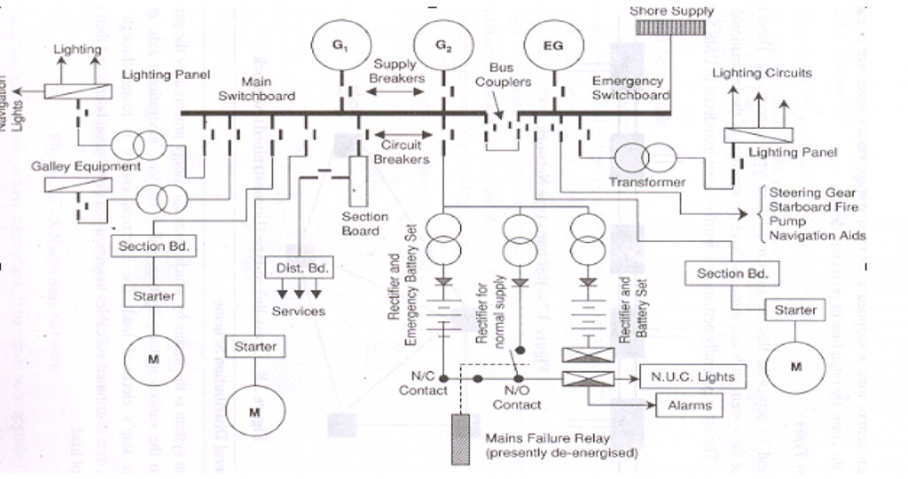
Sequence of event in case of mains failure
- Control and monitoring equipment of emergency generator on sensing a large drop in voltage or frequency sends a starting signal to emergency generator.
- Tie breaker between the main switchboard and emergency switchboard opens.
- In 45 sec the emergency generator starts and comes on load. During that time the supply for emergency lighting, alarm etc are maintained by the emergency batteries.
- In case emergency generator fails to come on load, these batteries can give power to selected lighting, communication and alarm circuits for minimum period of half an hour.
Busbar
In electrical power distribution system, a busbar is a metallic strip or bar that conducts electricity within a switchboard, distribution board or other electrical apparatus. Its main function is to conduct a substantial current of electricity, and not to be function as a structural member.
- In electrical power distribution system, a busbar is a metallic strip or bar that conducts electricity within a switchboard, distribution board or other electrical apparatus. Its main function is to conduct a substantial current of electricity, and not to be function as a structural member.
- The material composition and cross-sectional size of the busbar decide the maximum amount of current that can be safely carried.
- Busbar are produced in a variety of shapes such as flat strips, solid bars and rods, solid or hollow tubes, and braided wire. Some of these shapes allow heat to dissipate more efficiency due to their high surface area to cross-sectional area ratio.
- The skin effect makes 50-60Hz AC busbars more than about 8mm (0.31inch) thickness inefficient, so hollow or flat shapes are prevalent in high current applications. A hollow part has higher stiffness than a solid rod of equivalent current carrying capacity.
- A busbar should be rigid enough to support its own weight and forces imposed by mechanical vibration as well as accumulated precipitation in outdoor exposure. In addition, thermal expansion from temp. changes induced by ohmic heating and ambient temp. variations and magnetic forces induced by large currents should be considered.
How busbar are bolted
The first step is the surface preparation. Surface is thoroughly cleared, Roughened and grounded finish surface is preferred.
On the cleaned surface a thin petroleum jelly is applied so as to prevent oxidation. Sometimes lining before bolting is done. This gives good joint efficiency as well as reduce oxidation.
Bolting arrangements:-
- No. of bolts
- Size of bolts
- Bolts to be insulated and earthed.
- Distribution of bolts along with electrical and chemical and mechanical considerations should be taken into account. All these points ensure good joint efficiency.
Bolt Material: –
Galvanised steel , brass, bronze and copper alloy.
Bolt size varies from M6 to M12.
Bolt torque for each bolt size depends upon the material of the bolt and operating temp.
Busbar maybe connected to each other and to electrical apparatus by bolted, damped, riveted or welded connections. Conductor joint to be mechanically strong with relatively low resistance at the joint.
Types of joints:
- Welded Joint – Current carrying capacity being unimpaired as joint itself is a continuous copper conductor.
- Riveted Joint – Simple, Reliable, Versatile, Compact Disadvantages is that holes drilled on conductor with bolt distorts some of line current.
- Clamped Joint – Gives good joint efficiency if properly clamped.
Can be made in complete cross-section being unimpaired.
More mass at joints gives more efficiency cooling area.
Easy Installation
Disadvantages – Costly clamps and associated fittings.
- Soldered or brayed Joints – Hardly used unless reinforced with clamps or bolts as they weakened mechanically as well as electrically due to short circuit fault current.
Riveted joints are good if properly made, but difficult installation and difficult to remove or tighten in service.
Open or Dead front Switchboard
- Open Switchboard
Open switchboard are those in which all the essential components or equipment’s like circuit breaker, fuses, links and terminals are exposed on outside of an insulated base. For a.c. installation open switchboard is not permitted except for voltage of to earth
- Dead front Switchboard
All modern switchboard are dead front type in which all essential components are enclosed inside steel casing. The steel walls are incorporated within the switchboard is separate the section so that molten metal and arc from short circuit fault do not enter the neighboring sections. Only operating handles and indicator lamps are exposed outside.

 REQUIREMENTS")
