

MARINE FUEL CONTAMINANTS
Water
- Water, especially salt water, is objectionable in diesel fuel as it may cause injector and piston groove deposits and corrode engine components.
- Before burning the Fuel or blends are centrifuge to remove water and sediment.
- Salt water is the greatest single cause of fouling, deposits and corrosion, especially in the higher temperature areas of a diesel.
- Salt water can also cause excessive separator sludge volume as a result of water/sludge emulsification during centrifuging.
- Water can provide the beginning for microbial growth in heavy fuels.
- These very simple life forms live in the water and feed on the heavy fuel at the water-fuel interface.
- The result of microbial matter in the fuel can be a slime, which is sometime corrosive, which will foul strainers, filters and separators.
- Solution would be to add a “biocide” chemical additive to the fuel to kill the growth.
Sodium
- Sodium is an alkaline, metallic element that is found in the combined form of the common salt, NaCl.
- It is extremely active chemically.
- Salt water contamination in the barges used to transport the fuel is very common.
- Sodium in fuel is generally water soluble & can, therefore, be removed with the centrifugal separator.
- Sodium acts as a paste (flux) for vanadium slag.
- When unfavorable quantities of vanadium & sodium are present in a fuel then they form a molten form sodium/vanadium ash which can corrode alloy steels, and when this condition is allowed to persist unchecked, high temperature corrosion, overheating, and eventual burning away of exhaust valves, valve faces, and piston crowns occurs
- The main corrosive constituents in heavy fuel formed during combustion are vanadium pent oxide (V2O5), sodium sulphate, and other complex forms of these primary compounds.
- These compounds can damage exhaust valves turbocharger exhaust gas turbine and blading.
Catalytic Fines- Alumina/Silica
- They are hard, abrasive particles.
- It is also possible to contaminate a clean marine residual fuel oil with the catalyst particles during transport. For example, if steamship fuel (frequently containing catalyst particles) has been transported by the barge prior to moving a clean heavy fuel oil for the diesel powered ship, the barge bottom sediment will be mixed with the clean fuel oil & will contaminate it.
- Cat-fines are usually small, very hard, & quite abrasive to pumps, atomizers, piston rings & liners.
- (30 ppm) of alumina in the bunkered fuel oil is the upper limit for the successful treatment & engine operation.
- The average particle size, as well as the concentration, greatly impacts the wear rate of engine components.
- Small sized catalyst particles (1-10) micron range typically cause accelerated wear in injection pumps and injectors and only moderate increases in cylinder assembly wear, such as piston rings, piston grooves, and liners.
- The larger sized catalyst particles, in the ten to seventy (10-70) micron range, typically causes very accelerated wear rates in the cylinder assembly area. Also on injection pump inlet valves, exhaust valve seating areas, and turbocharger turbine blading.
Q How will you repair the coating in FWG & what coating is there on FWG?
Ans– The internal of the Fresh Water Generator is coated with 2 layers of Nordtec Ceramic 2212 FDA (Food grade coating). It is developed for Freshwater generators. It is designed as an abrasion resistant and fluid flow ceramic coating. It coating is reinforced with ceramic and carbide particles to obtain a high level of abrasion and erosion resistance and physical, mechanical strength.
The outside of the Fresh Water Generator, is primed and coated with two component paint.
As per manual – shell is coated with Neoprene coating and top cover- pure epoxy coating & bottom cover- Neoprene coating
Q What will be your action in case your FWG production reduced?- direct from manual- printed file
- Scale formation in evaporator
- Jacket cooling water temperature lower than prescribed
- Short cycling of jacket cooling water
- Air stay in evaporator
- Faulty solenoid valve
- Faulty flow-meter
- Check the vacuum
- Leakage in the plant like from pressure gauge, vent, distillate pump seal
- Scale formation in condenser
- Wrong order of fitting of plates in condenser.- fresh water stay in condenser or due to which fresh water produced goes to sea water.
- Incorrect feed
- Nozzle choked
- Ejector malfunctioning due to worn parts
- Faulty ejector nozzle
- Ejector pump problem- not developing pressure
- Filter before ejector pump dirty
- Distillate pump faulty
- Condenser cooling water flow reduced
- Condenser cooling water temperature too high
- If the temp of the shell is too high
- Ships draft is less
- Level of brine is too high
Osmosis- During natural osmosis, water flows from a less concentrated solution through semi permeable membrane to a more concentrated saline solution until concentrations on both sides of the membrane are equal.
- Gear pump or Reciprocating pump
- 60 bar pressure
- Chemical dosing- Sodium Hexametaphosphate sheets to assist washing the cartridge material
- Types of membrane- Cellulose acetate, aromatic polyamide membrane & polysulphonate
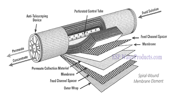
- Polyamide or polysulphonate (membrane not permeable to salt)- spirally wound- for Sea water
- Asymmetric membrane- Cellulose acetate membrane- hollow fine fiber- for brackish water
- Supported by Spiral wound cartridge
- Central Porous tube core for pure water.
- Many envelopes 2 type of membranes
- Envelopes separated by coarse gauge sheets
- Cartridge when open- appearance of opened book
- Everything is then packed in stainless steel cartridge
- Relief arrangement required for the system
- Chlorine in pure water is added for chlorination
- Sterilization of pure water
- De-chlorination- pure water passing through compressed carbon filter
- Output of pure water – increases- putting cartridge tube in parallel
- Quality of pure water- increases- putting cartridge tube in series
Pretreatment
Dosage- 5mg/ltr- inhibits precipitation of calcium carbonate. 10 micron cartridge filter used to reduce suspended solids in the membrane. Feed often heated to 40°C to improves output but most systems are designed for 25°C.
Post treatment
Sterilization by chlorination & to overcome flat taste soda ash can be used.
Safety device in RO system
- Sea water H.P relief valve
- Permate relief valve
- Conductivity meter
- D.P alarm
- L.P cutout
Advantages of RO system
- Small in size and light in weight
- Quiet operation
- Operation not effected by rough sea conditions
- Simple and fast maintenance
- No jacket water temperature is required
- Produce instantly
Disadvantage of RO system
- Careful pretreatment needed for long membrane life
- Membrane are expensive
- Output dependent on membrane condition
- For very high quality 2-pass system required
Reverse Osmosis Membrane: A reverse osmosis membrane has a thin microporous surface that rejects impurities, but allows water to pass through. The membrane rejects bacteria, pyrogens, and 85%-95% of inorganic solids. Polyvalent ions are rejected easier than monovalent ions. Organic solids with molecular weight greater than 300 are rejected by the membrane, but dissolved gases pass through.
Before purification TDS (total dissolved solid) allowed for this system is 45,000ppm and after purification it will be 300-1000 ppm. Material for reverse osmosis membrane is poly-sulphonate & polyamide.
Q What is steam trap and its use.
Ans– Steam traps are a type of automatic valve that removes condensate (i.e. condensed steam) and non-condensable gases such as air without letting steam escape. Steam traps are used to make sure that steam is not wasted. So basic function of steam trap is to trap the steam and remove the water & air. There are 3 basic principles on which steam trap works: Thermostatic, Density & Thermodynamic.
Thermostatic– Based on temperature of the 3 fluids. It opens for the cold fluid and close for the hot fluid. So for steam- hot fluid the thermodynamic element will expand and close the trap and hence trap the steam whereas for water (condensate) and air the thermodynamic element contracts and gets open to remove the condensate and air. Types are- Balanced pressure, expansion and bi-metal traps.
Density– Mechanical steam traps- Based on the difference in density of 3 fluids. It opens for higher density fluids (condensate & air) and closed for the lighter density-steam. Types are- Lever float, Free Float, Open Bucket & Inverted Bucket.
Thermodynamic– Based on the difference in velocity of 3 fluids. It opens for low velocity fluids (condensate & air) and closed for high velocity fluid- flash or live steam. Types are: Thermodynamic piston & Thermodynamic disc
On ships- bucket type, float type and bimetallic type are used.
Q For What Purpose are Steam Traps Installed?
Ans- Steam is formed when water vaporizes to form a gas. This is done by giving latent heat of vaporization to water. By this water will convert into vapor. When the work is done (i.e. steam has given up its latent heat), steam condenses and becomes condensate. Now the condensate will not be able to work same as the steam. So now the thermal efficiency will reduce as efficient steam is mixed with the condensate.
Q What is priming in boiler?
Ans- Priming in boiler is the carryover of varying amounts of droplets of water in the steam. It lowers the energy efficiency of the steam and leads to the deposit of salt particles on the super heaters and in the turbines.
Causes of priming in boilers
- Improper construction of boiler
- Excessive ratings
- Sudden fluctuations in steam demand
- Impurities in the boiler-water- foaming
- High level of boiler water
When this boiler water carryover is excessive, steam-carried solids produce turbine blade deposits. These conditions often lead to the super heater tube failures. Priming is related to the viscosity of the water & its tendency to foam. These properties are governed by the alkalinity, the presence of certain organic substances & by total salinity or TDS. The degree of priming also depends on the design of the boiler & its steaming rate.
Prevention of priming of the boiler
- Maintain the concentration of the solids in the boiler water at reasonably low levels
- Avoiding high water levels
- Avoid boiler loads
- Avoid sudden load changes
- Proper boiler design
- Very often contaminated condensate returned to the boiler system causes carry-over problems. In these cases the condensate should be temporarily wasted until the source of the contamination is found & eliminated.
- Use anti-foaming and anti-priming agents

 REQUIREMENTS")
