

Q Explain Reefer system on the ships.
Main Components of the Refrigeration plants
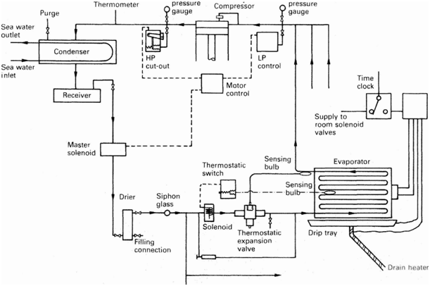
Any refrigeration system works with different components inline to each other in the series. The main components are:
- Compressor: Reciprocating single or two stage compressor is commonly used for compressing & supplying the refrigerant to the system.
- Condenser: Shell & tube type condenser is used to cool down the refrigerant in system.
- Receiver: The cooled refrigerant is supplied to the receiver, which is also used to drain out the refrigerant from the system for the maintenance purpose.
- Drier: The drier connected in the system consists of the silica gel to remove any moisture from the refrigerant.
- Solenoids: Different solenoid valves are used to control the flow of the refrigerant into the hold or room. Master solenoid is provided in the main line & other solenoid is present in all individual cargo hold or rooms.
- Expansion valve: An Expansion valve regulates the refrigerants to maintain the correct hold or the room temperature.
- Evaporator unit: The evaporator unit act as a heat exchanger to cool down the hold or room area by transferring heat to the refrigerant.
- Control unit: The control unit consist of a different safety & operating circuits for safe operation of the refer plant.
Working of a Ship’s Refrigeration Plant
The compressor acting as the circulation pump for refrigerant has two safety cut-outs- Low pressure (LP) & High Pressure (HP) cut outs. When the pressure on the suction side drops below the set valve, the control unit stops the compressor & when the pressure on the discharge side shoots up, the compressor trips.
LP or low pressure cut out is controlled automatically i.e. when the suction pressure drops, the compressor stops & when the suction pressure rises again, the control system starts the compressor. HP or high pressure cut out is provided with a manual reset
The hot compressed liquid is passed through a receiver through a condenser to cool it down. The receiver can be used to collect the refrigerant when any major repair work has to be done.
The master solenoid is installed after the receiver, which is controlled by the control unit. In case of sudden stoppage of the compressor, the master solenoid also closes, avoiding the flooding of the evaporator with refrigerant liquid.
The room or hold solenoid & thermostatic valve regulate the flow of the refrigerant in to the room to maintain the temperature of the room. For this, the expansion valve is controlled by the diaphragm movement due to the pressure variation which is operated by the bulb sensor filled with the expandable fluid installed at the evaporator outlet.
The thermostatic expansion valve supplies the correct amount of the refrigerants to evaporators where the refrigerants takes up the heat from the room & boils off into vapours resulting in the temperature drop for that room.
This is how temperature is maintained in the refrigeration plant of the ship.
Reefer compressor safety:-
- Low Pressure or LP cut off: This is a compressor safety which cut off the compressor in the event of the pressure drop in the suction line. The pressure of the suction line is continuously sensed by the control unit & when it goes below the set value, which means the room is properly cooled, the LP cut out will auto trip the compressor. When the pressure rises, indicating there is flow of the refrigerant in the line due to increase in the room temperature, the LP switch will start the compressor.
- High pressure or HP cut out: As the name suggests, the high pressure cut out activates & trips the compressor when the discharge side pressure increases above the limit value. The HP cut out is not auto reset & has to be done manually. The reason behind it is to manually attend the fault which is leading to rise in the pressure, else this situation can lead to overloading of the compressor parts and may damage the same.
- Oil differential cut out: This safety is again for the compressor as it is the only machinery in the circuit having rotational parts which requires continuous lubrication. In the event of the low supply or no supply of lube oil to the bearing, the differential pressure will increase & activates a trip signal to safeguard the bearing & crankshaft.
- Relief valves: Relief valves are fitted in the discharge side of the compressor & will lift and safeguard the compressor in the event of over pressure. One relief valve is also installed in the condenser refrigerant line to avoid damage to the condenser if there is high pressure in the discharge line.
- Solenoid valves: Master solenoid valve is installed in the common or main line after the condenser discharge. It closes when compressor stops or trips to avoid over flow of the refrigerant in to evaporator. All holds or rooms are fitted with individual solenoid valve which control the flow of refrigerant to that room.
- Oil heater: Oil heater is provided for the compressor crank case oil & prevents compressor from getting excessively cold which may effect the lubrication of the parts.
- Bursting disc in between suction & discharge- nickel with thickness 0.05mm. – pg-344 mc-G
- Fridge rooms high temp alarm
- Cooling water low press alarm
- Motor overload
- Safety spring valve in discharge valve which allow the complete lift of discharge valve when liquid enters in at suction & thus it shortcycle the refrigerant- pg-344 Mc-G
- Belt driven – (he will cross question any safety valve on head of comp in belt driven- NO)
- Relief valve on condenser
- Unloaders
Charging procedure for the reefer compressor
- Before doing anything take weight of the Gas bottle
- Start the compressor
- Collect the gas in the Receiver by closing the receiver outlet valve.
- The compressor will stop automatically due to the LP cutout once all the refrigerant is collected in the receiver
- Then connect the charging hose to the gas bottle
- Purge the hose by opening the gas valve
- Connect the hose to the charging point-IT is LOCATED AFTER THE RECIEVER OUTLET VALVE
- Open the liquid valve from the refrigerant charging bottle
- Compressor will cut in as the refrigerant flows all up the way through the expansion valve to the evaporator coil to the compressor & then to the receiver
- Check the desired level in the level gauge
- After disconnection again take weight of the gas bottle for measuring the amount of the gas charged
Purging done to recovery bottle as purging to air violates MARPOL Annex VI. The class surveyor who visited my ship was enquiring about the frequency of charging and then he told us about this.
Q Why belt slips in reefer compressor.
Ans– If there any liquid refrigerant enters in the compressor then to avoid damage to compressor parts due to hydraulic pressure belt will slip.
Q Short cycling of Refrigerant compressor.
- Undercharged system.
- LP cut out faulty
- LP cut out wrong setting
- Dirty condenser causing high pressure cut out.
- Compressor valve leaking- gas goes back to suction side
- Low air flow thru the evaporator.
- Thermostatic Expansion Valve chocked
- Solenoid v/v malfunctioning

 REQUIREMENTS")
