
Transformer is an electrical instrument that can transfers the electrical energy between two or more circuits through electromagnetic induction. Commonly, transformers are used to increase or decrease the voltage of a alternating current in electric power application.
A changing current in the transformer primary winding creates a changing magnetic Flux in the transformer core and a varying magnetic field impinging(affect) on the transformers secondary winding. This changing magnetic field at the secondary winding induces a changing electromotive force (EMF) or voltage in the secondary winding.
Transformer can thus be designed to efficiently change AC voltages from one voltage level to another within power networks.
Losses in transformer
An electrical transformer is a static device, hence mechanical losses likes (friction or winding losses) are absent in it. A transformer only consists of electrical losses i.e. iron losses and copper losses.
Core or Iron losses
Eddy current loss and hysteresis loss rely on the magnetic properties of the material used for the construction of core. Hence these losses are also called as core losses or iron losses.
i.e. Core or Iron loss —-> Hysteresis loss + Eddy Current loss
Hysteresis loss
Hysteresis loss is because of reversal of magnetization in the transformer core. Hysteresis loss depends on the volume and type of the iron, frequency of magnetic reversals and value of flux density.
Eddy Current Loss
In transformer AC current is given to the primary winding which sets up alternating magnetizing flux links with secondary winding, it produces induced emf in it. Some fraction of the flux get connected with other conducting parts like steel core or iron body or the transformer, which will result in induced emf in those parts, causing small circulating current in them. This current is called as eddy current. Because of these eddy currents, some energy will be dissipated in the form of heat.
Eddy Current Loss, We = PB2maxf2t2 watt
- Iron loss is constant for all loads.
- Iron loss depends only on supply voltage and its frequency.
- Iron loss can be minimized by using steel of high silicon content for core & by using very thin laminations.
- Iron loss is found from OC test.
- Input of the transformer when on no load(Zero Load) measures the core loss.
- i.e. Core Loss = Input power at No load
= V1I0Cos0
where, V1 = Supplied Voltage
I0 = No load current
Copper Loss
Copper loss is because of ohmic resistance of the transformer windings. Copper loss depends on load and is a variable loss
Total Copper loss = I12R1 + I22R2
Or Total copper loss = I12R01 (R01 = R1 +R21 = R1 + R2/K2)
Or Total copper loss = I22R02 (R02 = R2 + R11 = R2 + R1/(K1)2)
Copper loss is proportional to square of the current, and current depends on the load.
- Copper loss at half the full load is 1/4th of that at full load.
- Value of copper loss is determined from the short circuit test.
Hysteresis Loss
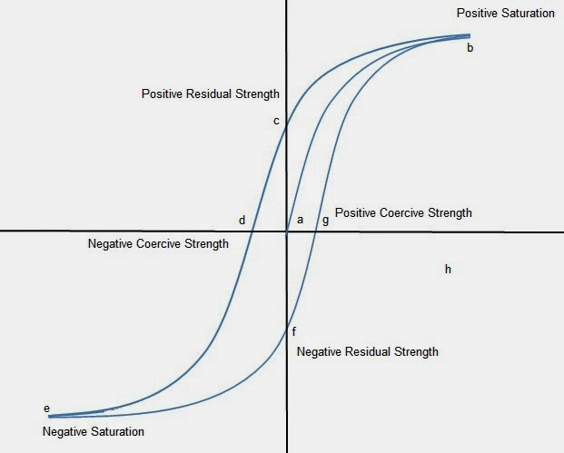
- A great deal of information about the magnetic properties of a material can be obtained by studying hysteresis loop or curve.
- It is a relationship between magnetic flux density(B) and the magnetizing current(H) also known as B-H curve. This curve is obtained by measuring the flux density of a material with changing magnetizing current.
- A ferromagnetic material which have never been magnetized flow the dash-line.
- As magnetizing current increases the magnetic flux density increases.
- At point ‘a’ almost all the magnetic domains are aligned and on further increase produce no or very little change and hence material has reached a point of magnetic saturation.
- On reducing current or H to zero curve moves from point ‘a’ to point ‘f’. Although H is zero still some amount of residual magnetism remain inside the material. It is known as point of retentivity and indicate the remainence of residual magnetism.
- As H is increased in –ve direction curve moves to point ‘c’ point of coercivity at this point enough of magnetic domains are flipped and curve reaches to point C and the flux density is reduced to zero.
- The reversed magnetizing force has flipped enough domains to reduce magnetic flux to zero.
- On further increasing magnetizing force the curve reaches point ‘d’ and again achieves point of magnetic saturation“same as above”
Why transformer rating in KVA
Copper loss of transformer depend on current and iron loss on voltage. Hence total transformer loss depends on voltage Amp. (VA) and not on phase angle formed between voltage and current i.e. it is independent of load power factor. Because of this reason rating of transformer is in KVA not in kw.
The load bearing capacity of a transformer varies in accordance with the power factor and thus kw is not a stable rating.
Kw = KVA * pf
Maintenance done on transformer
- Cleaning of dust dirt salts and ventilation duct.
- Cleaning of contact.
- IR testing
- Continuity testing of winding turns.
- Re-varnishing of windings.
- Tightness of housing and holding down bolts.
- Periodic checking of any loose connection of terminals on HV and LV side.
- Check grounding of transformer.
- Measurement of voltage ratio.
- Measurement of no load loss and current.
- Measurement of winding resistance.
Types of transformer
On the basis of construction
- Shell type
- Core type
on the basis of cooling
- Oil filled self cooled
- Oil filled water cooled
- Air blast type
Transformer efficiency
= Output/ Input = Output/(Output+Losses)
- Efficiency of a transformer will become maximum when copper loss and iron losses are equal.
Specification of welding transformer (Model UT300)
- Input voltage(V) = 380/415
- Phase = 2 lines of 3 phase
- Frequency (Hz) = 50
- Rating continues (KVA) = 16
- 60% duty cycle (KVA) = 24
- Open circuit voltage (v)= 80
- Operating Arc voltage (v) = 22-32
- Welding current range Min/Max (A) = 40-300
- Max. Hand welding current at 60% of duty cycle (A) = 300
- Max. continuous Automatic welding current at 100% of duty cycle A =200
- Welding electrode size (mm) = 2.6,3
- Switch fuse recommended (A) = 60
- Capacitor for power factor connection(KVAr) = 7
- Type of cooling = FAN
- Class of Insulation = H class
- Approximately weight = 100kg

 REQUIREMENTS")
