

- The variable delivery pump can run continuously in one direction, but have the cabpability of infinitely changeable discharge i.e., from zero to maximum in either direction.
- This is attained by changing the stroke of the pump piston. For small ruder movements, piston stroke is small and for full rudder movement the stroke becomes full.
- Normally variable delivery pumps are classified as
- Axial piston ( swash plate pump)
- Radial piston pump (hele-shawpump)
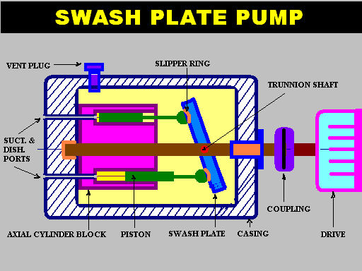
SWASH PLATE PUMP
- Construction :
- This has a circular cylinder block with axial cylinders on it’s pitch circle around the input shaft with which it revolves.
- The individual port holes terminate in a drilled port holes at the end face of the block with valve plate.
- The port holes are connected by external pipes to the steering cylinders.
OPERATION OF PUMP
- The driving shaft rotates the cylinder barrel and piston.
- The external trunnion shaft enables the swash plate to be moved about it’s axis.
- When the swash plate is in vertical position, no pumping takes place.
- When swash plate is tilted to one direction one side port becomes suction and the other port on other side of the centreline, become discharge because of the pumping action.
- For opposite direction of tilt, the direction of flow is reversed.
- Stroke length of the piston and hence the quantity of flow of fluid depend on the angle of tilt of the swash plate.
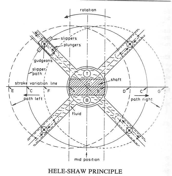
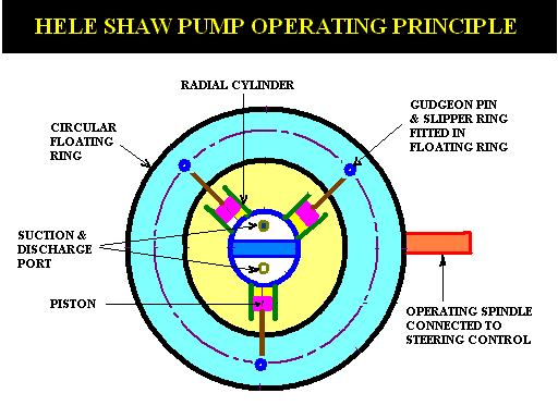
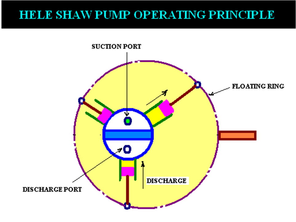
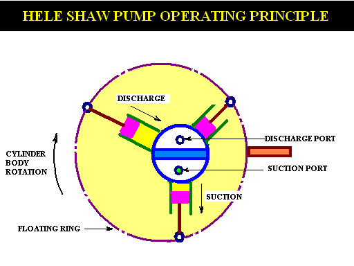
HELE SHAW PUMP
- CONSTRUCTION :
- The circular cylinder body driven by constant speed electric motor rotates around a central valve (tube) arrangement.
- The cylider body is supported by ball bearings which are installed on inner side of the body casing.
- The cylinder body is connected to the central valve arrangement by ports, which are further connected to the outer casing and finally to the ram cylinders for supply & delivery of oil
- A number of piston fit in to the radial cylinders & these pistons are fastened to slipper rings by gudgeon pins.
- The slipper rings fit in to the circular track (grove) in floating ring.
- The floating ring is supported by ball bearings on either side, which are further installed on a guide block.
- The guide block attached with the control rod can be moved horizontally at right angle to the pump shaft axis.
- Two spindles which pass out of the pump casing is attached to the guide block, control the movement of the floating ring.
- Pump is usually provided with odd number of cylinders, usually seven or nine to produce even hydraulic flow and better pump balance.

 REQUIREMENTS")
