

The NOx(Nitrogen oxide) control requirements of Annex VI applies to installed marine diesel engine of over 130 kW output power other than those used solely for emergency purposes irrespective of the tonnage of the ship onto which such engines are fitted.
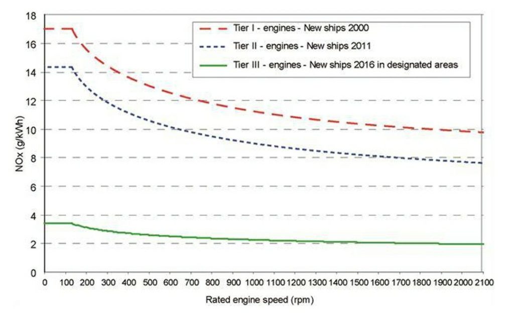
Most Tier I engines have been certified to the earlier, 1997, version of the NOx Technical Code. The emission value for the diesel engine is to be determined in accordance with the NOx Technical Code 2008 in the case of Tier II and Tier III limits.
The Tier II limits must be met globally by all ships constructed January 1st 2011 or later. Tier III limits are local requirements to be met in designated NOX Emission Control Area by ship constructed on or after the ECA designation date. The present NOX ECA and dates are listed
North America US/Canada – 200 naut. mile w.e.f 1st Jan 2016
Northern Europe Baltic sea, North sea & English channel w.e.f 1st Jan 2021
The Tier III controls apply only to those ships who is operating in Emission Control Areas accepted to limit NOx emissions, outside such areas the Tier II controls apply.
A marine diesel engine that is fitted on a ship constructed on or after 1 January 2016 and operating in the North American ECA and the United States Caribbean Sea ECA shall follow with the Tier III NOx standards.
As you are well aware , Nox is formed due to chemical reaction between Nitrogen and oxygen. It has been observed that Nox is formed in combustion chamber temp reaches around 1100 deg. C Whenever combustion takes place the Temperature is reaches around 2000 deg. C Meaning technically we can not develop the Engine with zero NOx but. Nox production will be depending on time for which the temp is above 1100 in combustion chamber ” Resident time ” or oxygen quantity , less the oxygen available less will be the NOX form .
A. PRIMARY MEASURES ( Before Combustion take place)
1. Optimized combustion-chamber
Geometry for better combustion and avoidance of temperature peaks that produce NOx formation
2. Optimized fuel injection
• Delayed fuel injection: – Retarded fuel injection timing leads to lower peak pressures and maximum temperatures and hence a reduction in NOx.
•Common rail control :Use of electronic fuel injection system and rate shaping of fuel injection, results in a reduction in NOx. injection of small amount of fuel before TDC just to take care of Ignition delay, temp is high enough then bulk fuel after TDC is injected results in immediate burning of fuel,piston is forced down, volume increases and pressure rise is also limited and therefore the temperature.
• NOx optimized fuel spray pattern: – Use of NOx optimized nozzles and slide type fuel valves (zero sac volume)
• By making use of Miller cycle in 4-Stroke engines along with high efficiency turbocharger, and varying the closing of inlet valves closed earlier before BDC which reduces the compression and peak pressures and thus the NOx production. This NOx reduction method will need two turbochargers (2-Stage turbocharging). In case of 2-stroke engines, VEC (variable exhaust closing) is used.
3. Water addition
In this method, water is added to decrease the temperature of combustion leading to low NOx emission. In water emulsion, fuel is mixed with water & in water injection a separate fresh water injector is mounted in the cylinder head which injects water. This method has a drawback of increasing the specific fuel oil combustion with reduction in NOx by only 20-45%., thermal efficiency reduces, corrosion problems.
4. Combustion air treatment
• Humid air method:In this method, water vapor is mixed in the combustion air before supplying it to the cylinder. Air from the Turbocharger blower is passed through a cell that humidifies and chills the hot air taking moisture from the cooling water until air saturation is achieved. Generally saline sea water is utilized in this method by heating it with jacket water and turbo charger heat, and the left over brine is disposed back to the sea. This method can achieve reduction of NOx(Nitrogen oxide) by 70-80%.
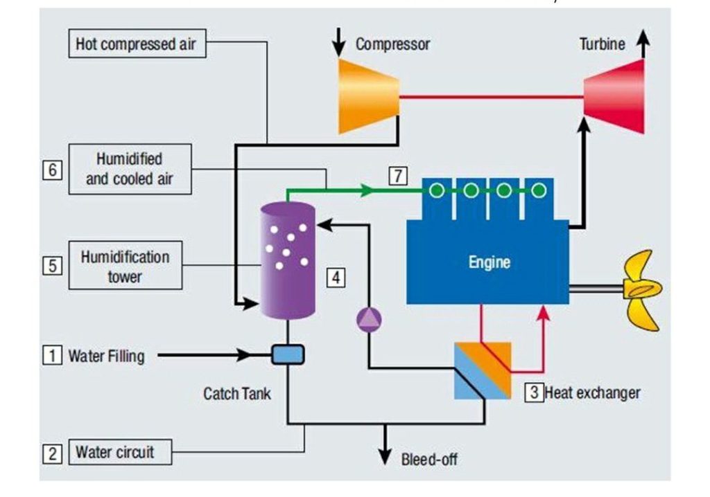
SCAVENGE AIR MOISTURIZING
• The SAM system has a seawater injection stage, where a surplus of seawater is injected for saturation and cooling of the hot air from the compressor.
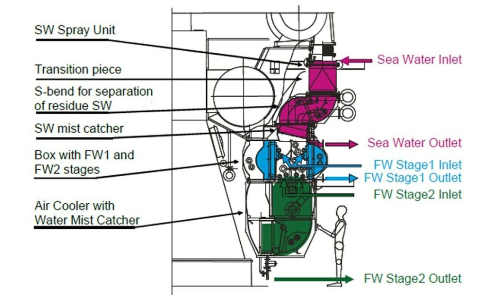
• The sea water stage will provide nearly 100% humidification of the scavenge air and supply all of the water for humidification • The freshwater stages 1 & 2 shall be near temperature which is neutral to the scavenge air and create a small freshwater production depending on the operation parameters chosen.
• The freshwater stages only act as a cleaning stages for removal of any salt which may pass with the air from the seawater stage. A continuous build up of salt in the freshwater stages would eventually cause the salt content to reach an unacceptably high level.
• This is counteracted by cooling the saturated air with the air cooler and generating some extra freshwater for stage 2. The extra freshwater is then sent upstream on the tank side of the SAM system. Thereby the content of salt in the freshwater stages can be controlled. • The mass flow of water entering the combustion chamber in the scavenge air is controlled by the temperature of the scavenge air. The temperature of the scavenge air is controlled by the cooling water temperature of the air coolers. All of the evaporated seawater could, be condensed again in the air cooler. The engine performance would then correspond to operation in humid tropical regions.
• The presence of the highest possible absolute humidity in the scavenge air is wanted, as this reduces the formation of NOx emissions. The intention is, therefore, to cool the scavenge air only sufficiently to generate the necessary freshwater for keeping the salt content in the freshwater stages down, and take as much water as possible into the engine process
• Water cooled rest gas
In an electronically regulated exhaust valve timing it is quite easy to leave some of the exhaust gas in the cylinder. Due to this exhaust gas there is negative impact on engine performance, but this can be dramatically reduced by cooling the rest gas with a water spray, in which case the rest gas responsible for some of the NOx reduction and the water spray for the rest.
SECONDARY MEASURES (after combustion take place )
Possible undesirable of primary measures are reduced overall energy efficiency, increased carbon mono-oxide and soot formation and hydrocarbon emission, corrosion due to reducing atmosphere, increase in unburnt carbon in fly ash. Hence, this directly affects the combustion process and some measures can also damage the engine components. The secondary measures does not affect the engine component and combustion process.
SCR (Selective catalytic reduction)
The SCR is the most systematic method to reduce NOx emissions from ships (up to 90-95% of reduction). In this method, fuel oil containing low sulphur is used and exhaust temperature is maintained above 300 deg C. The exhaust gas is mixed with water solution of urea and then it is passed through catalytic reactor.
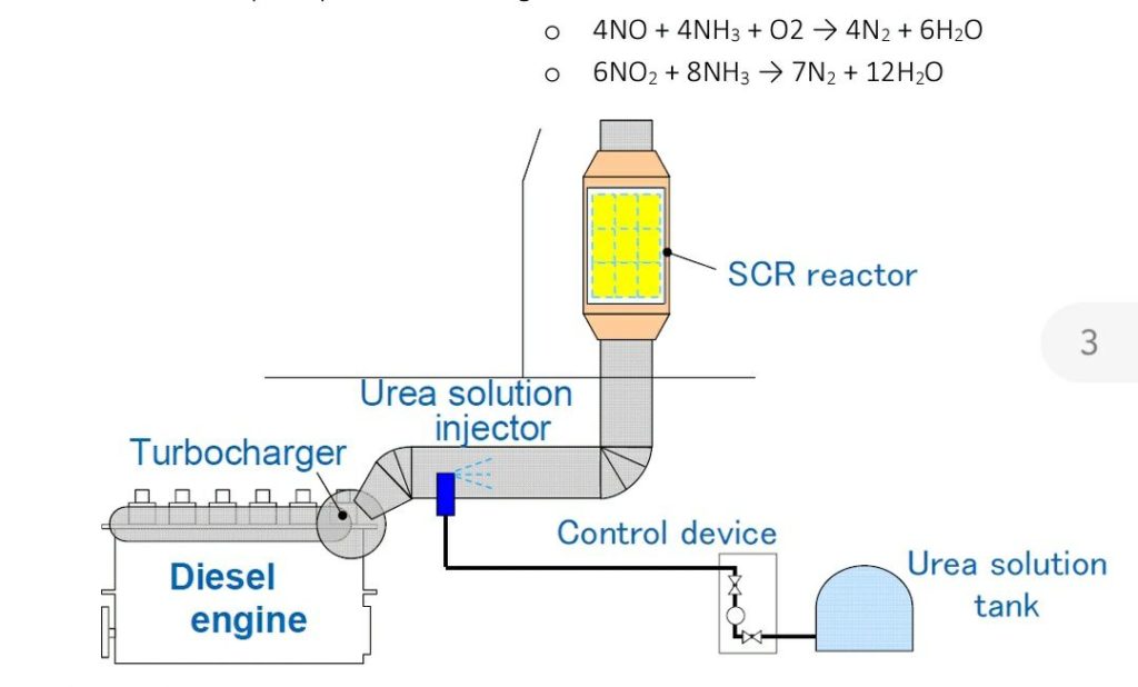
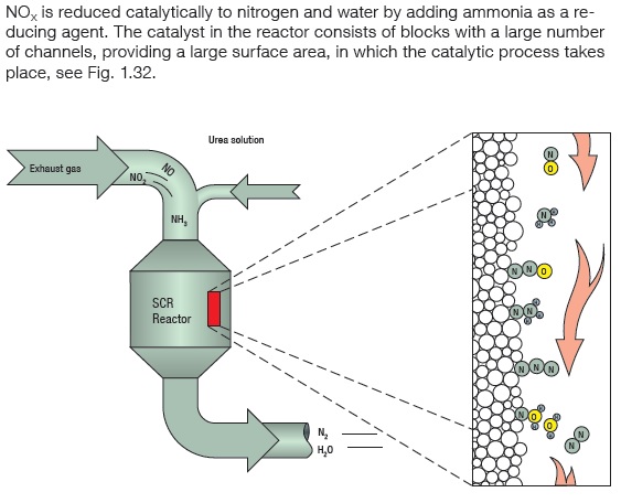
The only disadvantage of SCR is its expansive installation and operating cost. Catalysts are normally prepared of different ceramic materials which is used as a carrier, such as titanium oxide, and active catalytic components are usually either oxides of base metals zeolites, or various precious metals.
The reactions are, in principle, the following
o 4NO + 4NH3 + O2 → 4N2 + 6H2O
o 6NO2 + 8NH3 → 7N2 + 12H2O
SNCR (Selective non catalytic reduction): –
In case of SNCR, the reaction between NH3 & NOx takes place in a gaseous phase in a temperature window of between 800 and 900 deg Celsius.
The most effective method of NOx reduction in secondary measure.
The advantages are:-
1) Secondary measures reduces Nox in case of SCR of up to 90- 95% and in case of SNCR 30-50%. But, primary measures average Nox reduction is up to 25- 35%.
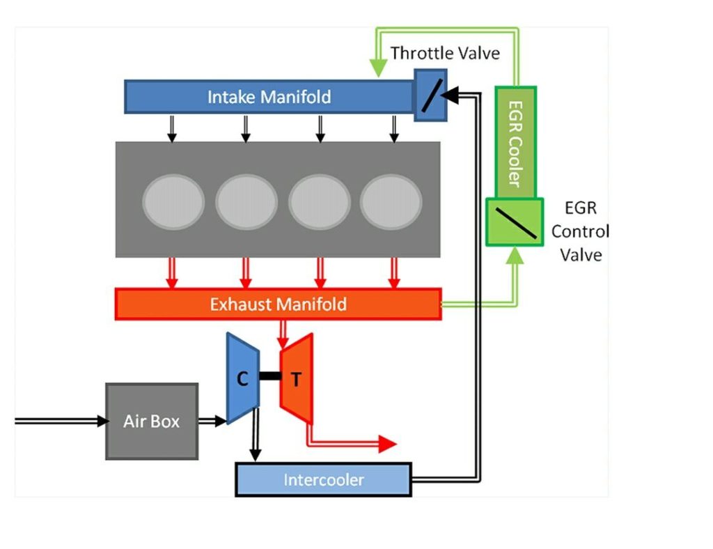
EXHAUST GAS RECIRCULATION
• A portion of the exhaust gas from the main engine exhaust receiver is recirculated to the scavenge air via a dedicated closed loop scrubber.
• O2 in the scavenge air is thereby reduced.
• CO2 has a higher heat capacity than O2 which reduces peak temperatures in the cylinder.
• Reduced O2 content in the scavenge air reduces the combustion speed which reduces peak temperatures in the cylinder and hence the NOx formation.
EGR METHOD MAN B&W LATEST
The requirement for controlling the engine in Tier III mode is triggered when the ship is sailing inside a NOX Emission Control Area. The operator must assure that the engine is operated in accordance with the requirements. Tier III compliance could be documented using a logging system but this is not part of the engine control system.
To ease this, MAN B&W engines are equipped with an engine control system which delivers signal output documenting the emission mode status of the engine.
Two Tier III compliance status signals are available:
‘Tier III system started’. This signal is activated when ,
1) a Tier III mode command has been given to the engine control system,
2) the Tier III system is working
‘NOX reduction active’. This signal is activated when NOX reduction begins The first signal allows for logging when a Tier III mode command is issued by the ship crew, the second allows for logging when the engine is normally operating at reduced NOX emission level. The difference between the two signals is caused by startup time or by specific operating conditions.
Certain cases will result in non-error situations where the operator has issued a command and the system is not reducing NOX.
This could happen in the following situations:
Engine load change is quicker than the guidance load change curve
Rough sea conditions resulting in oscillating engine load
Time during engaging and dis-engaging of control valves
Engine load or ambient conditions outside the operating window of the emission Control system as specified in the NOX Technical File
Tier III systems are designed to minimize these cases as far as possible. As the engine is Tier III certified, and these are transient situations not covered by the certification cycle, the engine is still considered to be in Tier III mode although NOX reduction is not occurring. In case of system failures, the engine control system will issue an alarm code and text, allowing for the situation to be corrected. Both Tier III compliance signals are removed.
Two dissimilar matching methods are used for the EGR systems:
EGR with bypass, configured with only one turbocharger and used for engines of bore 70 or less.
EGR with Turbocharger cut-out matching, configured with two or more turbochargers and used for engines of bore 80 or greater
Bypass matching
An EGR system arranged with the bypass match up is shown Two strings, a main string and an EGR string, are available to direct the scavenge air into the scavenge air receiver:
the main string, with the capacity to lead all the scavenge air through the turbocharger compressor and the scavenge air cooler.
the EGR string, with the capacity to lead up to 40% of the exhaust gas through the pre-spray and the EGR unit (EGR cooler and WMC) to a mixing point in the main string.
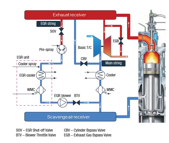
Two modes are available for bypass matching:
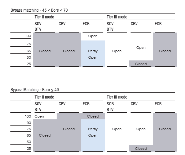
Tier II mode
In Tier II mode only the main string is in operation. The valves in the EGR
string (SOV/BTV) and the cylinder bypass (CBV) is kept closed. In this mode,
the exhaust gas bypass (EGB) is fully open at high loads and partly open at
low loads to balance the turbocharger. However, on engines with a bore of
40 or less, the exhaust gas bypass will be closed at high loads and the EGR
string open, to obtain sufficient scavenge air pressure while meeting restrictions on the turbocharger speed.
Tier III mode
In Tier II mode only the main string is in working condition. The valves given in the EGR string (SOV/BTV) and the cylinder bypass (CBV) is kept closed. In this mode, the exhaust gas bypass (EGB) is fully open at high loads and partly open at low loads to balance the turbocharger. But, on engines with a bore of 40 or less(<), the exhaust gas bypass will be closed at high loads and the EGR string open, to get sufficient scavenge air pressure while meeting restrictions on the turbocharger speed.
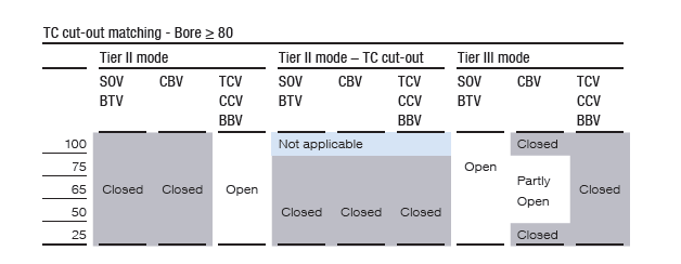
TC Cutout matching
An EGR system with Turbocharger cut-out matching is shown in the diagram in 3 strings, a main string, a cut-out string and an EGR string, are available in the system to direct the scavenge air into the scavenge air receiver:
the main string, leads up to 70% of the scavenge air through the basic turbocharger and the scavenge air cooler.
the cut-out string, leads up to 40% of the scavenge air through the cut-out turbocharger and through the EGR unit (EGR cooler and WMC) before entering the scavenge air receiver through the balance pipe.
the EGR string, accounts for up to 40% of the exhaust gas through a pre-spray and EGR unit to a mixing point in the main string, forced by one or more EGR blowers. In this case the cut-out string is closed.
On some larger engines, a design with more than two turbochargers will be needed. The principle is unaltered although the number of turbochargers and EGR units are increased.
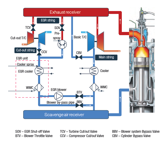
Tier II mode
In Tier II mode the main string and the cut-out string are in operation. The TC cut-out valves (TCV/CCV) and the blower by-pass valves (BBV) are open, while the EGR string is kept closed by the EGR shut-off valve and the blower throttle valve (SOV/BTV). In this mode the EGR cooler perform as a normal scavenge air cooler. Around 40% of the scavenge air is passed through the cut-out string, the remaining 60% through the main string. The cylinder bypass is kept close in this mode.
Tier II mode – TC cut-out
The cut out string gives a chance to run the engine in Tier II mode at low loads with a TC cut-out and the SFOC could thereby be reduced. In this condition only the main string will be open, while the cylinder bypass (CBV) is kept closed.
Tier III mode
In Tier III mode the cut-out string is closed (TCV/CCV). The EGR string is opened by the EGR shut-off valve and the blower throttle valve (SOV/BTV). The exhaust gas is pass through the pre-spray and the EGR unit to the mixing point and the scavenge air receiver, forced by the EGR blowers. The EGR ratio is adjust by changing the flow of the EGR blower. The cylinder bypass is partly active in this mode to increase the scavenge air pressure and thereby reduce the SFOC.


