

BASIC REQUIREMENTS
The functional requirements for the Engine Control System (ECS) are dictated by thermodynamic and other (mechanical, tribological) functional requirements. Apart from several core functions which every ECS has to perform for the electronically controlled reciprocating engine, the ECS of the marine two-stroke low-speed engine has to fulfil additional requirements:
- Compliance with environmental and Classification Society rules
- A single ECS for both Diesel & DF engines
- Modular hardware layout allowing prefabrication of the engine sub-assemblies(e.g. Rail Unit)
- Simple & cost efficient hardware installation for the engine builders & Shipyards
- User friendliness for commissioning personnel as well as for the Operators/Crews
- Local and remote diagnostic possibilities
- Redundancy and electromagnetic compatibility
- Low power consumption
- Low cost, long lifetime, retrofitability & a thoroughly planned obsolesce concept
ENGINE CONTROL SYSTEM SOFTWARE ARCHITECTURE
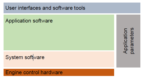
The engine control system software of a marine Diesel engine comprises four elements:
- System/platform software: the interface between the engine hardware17 and the application software
- Application software: software controlling core engine functions
- Application parameters: the engine-dependent values embedded in the application software
- User interfaces and software tools: interfaces between engine and user and other software tools
DEVELOPMENT PROCESS: FROM REQUIREMENTS TO SOFTWARE
The development process for the control system software is carried out according to the so called V-process. The following graph visualises relations & dependencies between development steps from requirements gathering & formulation to final validation:
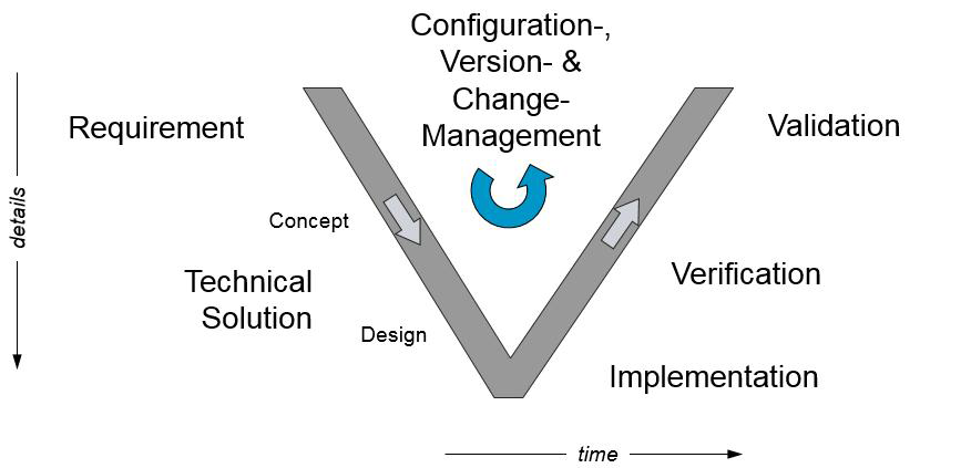
The process will be explained in more detail in the steps below, referring to the abovementioned four elements.
1. System / platform software development: The platform software development starts with requirements analysis and processes’ definition. Particulars such as sampling rates (e.g. crank angle 1kHz), task rates (e.g. 100Hz starting air pilot valve control) & transmission priorities(e.g. highest priority on CAN-Bus is fuel command due to speed regulation) are decided at this stage for all coexisting applications and internal level processes. A wide range of parameters and dynamic behaviours have to be considered, such as engine speeds, acceleration/deceleration ratios, etc, since a single
ECS covers an entire portfolio of engines. Initial tests and software performance optimisations are performed on the laboratory simulators. When μControllers, processors & the transmission busload are optimised & software operations are validated the next level of testing takes place on the test engine and later on the production engines.
2. Application software: The application software is the core knowledge of the engine developer. The development process starts with requirements definition; based on this the definition of the control concept is started and the design is done in a Simulink model. This model is then optimised through several iterations and tests in Simulink environment. After compilation to processor/μController code, the optimised Simulink model is tested on the laboratory simulator on the real hardware control modules. After successful testing on the simulator, the application is subject to final validation on the test engine and later on the production engine.
3. Parameters definition: This element begins with process definition, including Simulink modelling and establishing a theoretically safe range of parameters for the particular process and application (e.g. overlap of fuel injection with exhaust valve opening not allowed). Subsequently, the first attempt to classify parameters into predefined groups takes place. Parameters are grouped in regards to i) their nature: engine(bore) size-specific, engine cylinder configuration-specific, & installation(i.e. tuning) specific, and ii) their accessibility: expert level editable, commissioning
level editable, operator level editable. The initial setup of parameters is then crosschecked on the laboratory simulator and later optimised on the test engine where safe-ranging (allowed for certain level of accessibility) is finally validated. Final grouping of parameters is reviewed with a commissioning team and operational experts who contribute to the creation of commissioning procedures.
4. Interfaces and software tools development: The development of the operator’s interface is based on available functions of the Graphical User Interface (GUI) and particular needs of an engine (e.g. a DF engine needs a much more complex interface than the Diesel engine). Particularly important for this element is classification rules, ergonomics & considerations about marine practice. Commissioning and debugging tools are developed and reviewed with relevant software experts as well as operational experts experienced in field activities. Finally, comprehensive manuals are created.
MODERN CONTROL SYSTEM HARDWARE ARCHITECTURE: PERCULIARITIES OVER OTHER INDUSTRIAL ENGINES
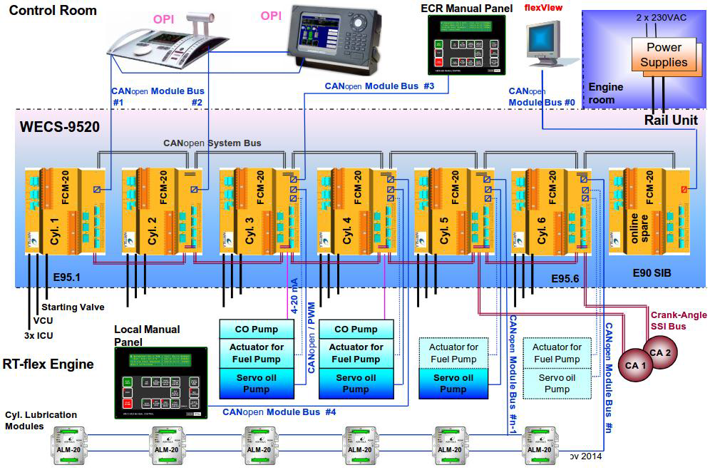
Due to the nature of its application as a single prime mover and the corresponding classification requirements, a marine engine has to demonstrate high redundancy and reliability; features that greatly affect the architecture of its ECS. A high level of redundancy is, however, accompanied by high complexity and cost; therein lies the main trade off in choice of engine control system architecture. The two extremes are split Intelligence Systems(SIS) & Centralised Intelligence Systems (CIS), examples of which are shown below.
The SIS is characterised by the absence of a particular hardware module which plays a role of the main computational and communication interface. All modules are equal & are processing & controlling assigned own cylinder functions (e.g. fuel injection) & common tasks (e.g. fuel pressure regulation, external communication, etc).
In CIS there are at least two different type of hardware modules: main & cylinder control modules. Typically (for redundancy reasons), there are two main modules which are acting communication masters for internal Bus communication & as interfaces to external systems. These two modules store the software package for the entire system, process & sometimes also control common regulation tasks for the entire engine.
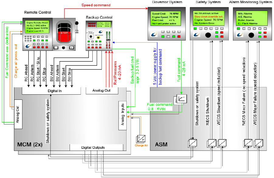
Overall, SIS offer very good redundancy, however that is often at the expense of hardware utilisation. On the other hand, CIS systems usually offer better utilisation of hardware but require more data to be transmitted across the control system. Appropriate combination of specific features of these two architectures (and other, such as commonality of modules, obsolescence management, etc) provides a good base for achieving competitive cost level for a specified redundancy level.

 REQUIREMENTS")
