

It is not usually known that the first airless injection system i.e. not to use compressed air or to atomise the fuel; was a common rail system. The development of this system is often mistakenly given to Doxford, but it was invented & patented by the Vickers of Barrow in Furness. In the early common rail system the engine driven fuel pumps pressurized a fuel rail to around 400 bar from which pipes led to the fuel valves operated by the cams & rocking levers. Independently driven pumps were given to prime the system for starting.
Later systems used hydraulically operated injectors, the delivery of the fuel being controlled by the cam operated valve. Fuel quantity was regulated by an eccentric on the cam follower. With the inclusion of industrial electronics into marine engineering systems coupled with the giant strides made in the evolution of computer technology, it has now become feasible to re-introduce the fuel injection common rail along with other fuel injection systems, using this modern technology to time the injection of the fuel without mechanical aids. It has become possible to distribute with the timed camshaft altogether by using similar systems to regulate operation of valves & the air start system.
The two vital manufacturers of two stroke crosshead engines have both developed a camshaft-less engine. Sulzer call theirs the RT Flex engine, & MAN B&W call theirs the ME intelligent engine. Both the engines utilizes electrical & engine driven axial piston pumps to pressurize servo oil rails to around 200 bar which are then used for fuel injection & exhaust valve function. MAN B&W utilizes the servo oil to drive the cylinder lubricator units(Alpha system)
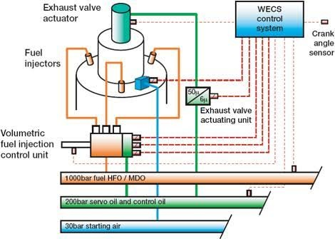
However, they both work without a camshaft & use computers to regulate, fuel injection, exhaust valve operation & air starting, the process of fuel injection is different. Sulzer use a pressurized fuel rail using a set of the jerk type pumps driven by a 3 lobe cam geared to the crankshaft. The pumps are variable delivery, based on the ZA40 fuel pump, regulated by an electrically driven fuel pump shaft connected to the engine computer. The engine computer system called as the Wartsila Engine Control System WECS; regulates the delivery from the common rail to the individual cylinders via the volumetric injection control system which utilizes finely filtered engine LO pressurized by an electric pumps to around 200 bar. When the Rail Valves are energized for the injection by the Valve Driver Module, oil from the Control Rail opens the Injection Control Valves. The fuel injectors are pressurized & fuel oil pressure behind the Fuel Quantity Piston keeps this pressure at the injectors. As the Piston proceeds to the left a feedback signal is sent to the Cylinder Control Module.
At low engine load condition the control system cuts out one of the three injection valves per cylinder. At very low load condition two of the three injection valves are cut out. This is used to prevent visible smoke emission & to reduce fuel consumption. It is possible to decrease engine load to 10% with engine revolutions as low as 7 rpm. Unlike the Sulzer RT Flex engine the MAN B&W ME engine doesn’t run the fuel injection on the common rail system. Alternatively a solenoid operated proportioning valve(the FIVA valve – Fuel Injection Valve Activation) permits the pressurized servo oil under a hydraulic piston. This then proceeds the fuel pump piston upside, raising the fuel pressure & opening the injection valves.
A nitrogen filled accumulator keeps the hydraulic servo oil pressure during the operation of the pump. In order to time the fuel injection the Control Systems must know the exact crank angle of the individual units. To do this two crank angle sensors are installed at the free end of the engine. These sensors are precise to 0.1°. Cylinder pressures & powers are continuously observed by using strain gauges fitted into the cylinder head, & the computer automatically adjusts for twist in the crankshaft when relating with the crankshaft position to cylinder pressure. the systems provide complete freedom over start & end of injection & consider fuel quality, dead time(the time between injection start command being given & actual injection), & Variable Injection Timing (VIT).
The exhaust valve actuator take the place of the cam operated exhaust valve hydraulic pump on both make of camshaft less engines. Both working on the similar principle, servo oil at around 200 bar is utilized to control the piston which controls the exhaust valve “hydraulic push rod” The oil for controlling the “hydraulic push rod” comes from the main engine LO supply through the non return valve. The air start system is equivalent to that on the conventional engine except there is no need for the mechanically driven distributor to open the air start valves at the correct time. Instead of the camshaft driven, reversing air start distributor, each air start valve is opened at the correct time by the engine computers sending a signal to the solenoid controlled nc(normally closed) valve. The timing of the air start valves will change depending on the number of cylinders, but they will be open for a long enough period to enable overlap, so that a valve opens before the previous valve closes, enabling starting from any position of rest. The nominal opening can be regarded as 0° (ie TDC) & closing at 110° ATDC. The computer senses when to send the signal because it is receiving information as to the crankshaft position from the angle encoders which calculates crankshaft position & rpm. When the engine has attained firing speed the computers shut off the air & introduce the fuel.
This gives a brief summary of the computer controlled camshaft less engine.

 REQUIREMENTS")
