

REQUIREMENTS
The requirements for the hot part components are diverse and often conflicting with each other. Component temperatures of 600 °C and above presuppose the correct material selection and a proper cooling. The thermal stresses, caused by the temperature gradients, have to be considered in the low-cycle behaviour analysis. The components around the combustion space are bolted together with elastic studs, which are pre-tensioned such that no leakage and no dynamic sliding between the components occurs. Ultimately, the level of dynamic stress in the different components, induced by the cylinder pressure, may not exceed the set limits.
One of the main contributors to the reliability of a two-stroke marine Diesel engine is the piston running behaviour, which is directly linked to the design of the hot parts. The standard measures applied on modern Wartsila engines have already been verified for many years. They include:
- Liner of the appropriate material
- Careful turning and deep plateau honing of the liner running surface for fast and trouble-free running-in
- Three chromium-ceramic coated, pre-profiled piston rings
- Chromium layer with ample thickness in the piston ring grooves
- Anti-polishing ring at the top of the cylinder liner to scrape off deposits on the piston crown
- Removal of condensed water from the scavenge air by underslung and water separator
- Cylinder lubrication by the Wartsila Pulse Lubricating System (PLS)
DEVELOPMENT PROCESS
- In a first step the concepts (e.g. cylinder liner with or without bore-cooling) and main dimensions are defined based on existing similar engines with inputs such as stroke-to-bore, compression ratio, port geometry and cylinder pressure from thermodynamic layout
- The concepts are then verified and the dimensions defined in several iteration circles. With first input from piston running experts, proposals are made for the combustion chamber design, exhaust duct angle, cylinder jacket, piston height, piston cooling, etc
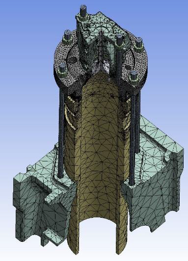
- Starting from the cylinder liner and cover only, quasi-static stress calculations with forces and temperature influence are made and gradually refined to include the surrounding components such as cylinder jacket and exhaust valve. An example of a such a calculation model is shown in figure
- The stress calculations are iterated with CFD calculations for cooling efficiency of the parts
- Stress & hydrodynamic(piston rings) calculations of are carried on piston running components.
- The layout of the entire exhaust valve drive is done in parallel with the hydraulic layout to determine the dimensions of the actuator piston and the maximal hydraulic pressures, which are used for the mechanical calculations of the actuator housing. The valve cage is optimised taking into account mechanical loads and deformations by means of FE-calculation
- As the final step, the hot parts are checked for the compatibility with the surrounding engine structure components
CONCEPT, DESIGN AND MATERIAL CHOICES
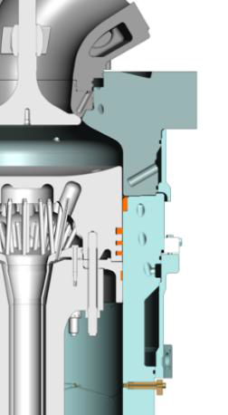
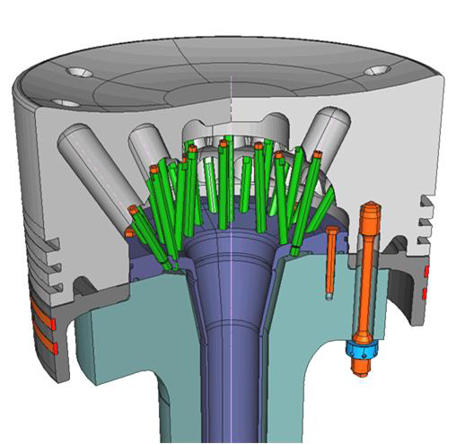
- Cylinder liner & cover: The uppermost part of the cylinder liner is highly thermally and mechanically loaded since it is directly exposed to the combustion. The required cooling effect and part rigidity can be achieved by a thick collar with a row of cooling bores and water as coolant. Only the smallest engines have a more simple cylindrical cooling water space. The figure below illustrates the two cooling principles.

The cylinder liners are made up from the grey cast iron alloy which offers the best compromise between manufacturability, piston running behaviour and mechanical properties.
The free-standing cylinder liner is „sandwiched“ between the cylinder block and the cylinder cover by the cylinder cover studs. The bolts are pretensioned so that most of the dynamic stress induced by the cylinder pressure is experienced as a relaxation in the compression of the cylinder liner instead of a strain on the studs. The pre-tension force of the cylinder cover studs has to be determined very carefully as the cylinder cover acts as relief valve of the combustion space: it needs to be tight during normal operation but has to lift-off before major engine components (piston or connecting rod) are damaged due to excessive cylinder pressures (e.g. >130% of layout pressure). Additionally no dynamic sliding is allowed between the cylinder cover & the liner.
Piston: Finding the proper cooling is one of the main challenges for the piston designer. With the so called jet-shaker cooling principle(see Figure below), which is applied on the most Wärtsilä engines, it is possible to keep the temperatures below the limit on the combustion space side as well as in cooling bores. Too high temperatures at the piston top would lead to the material losses due to the corrosive attack from the combustion gases. Excessive temperatures in the cooling space can result in carbon deposit build-up with negative consequences to the cooling efficiency. For a reliable engine performance , it is also essential to keep the temperatures around the piston rings within a certain range.
The piston is exposed to pressures up to 200 bar, so it is designed such that the stresses and deformations caused by the combustion forces remain within the limits. The main piston components: piston head, skirt and rod including their bolting have to be designed very carefully to avoid any dynamic sliding at the joint faces.
- Exhaust Valve: The diameter of the exhaust valve is one of the first parameters that is determined for a new engine type as it is significant for the thermodynamic layout. Today the diameter of the valve disc is typically in the range of 0.5x bore diameter; a good compromise between engine performance, manufacturing cost and power demand for the valve drive. The temperatures of the exhaust valve spindle typically reach more than 600 °C since there is no cooling of the spindle itself. Excessive material loss on the combustion space due to high temperature corrosion can only be prevented by the use of high alloy steels (including high chromium content) or equivalent welded protection layers (seen mostly on recent engines). By employing a careful design of the exhaust valve spindle and seat, the relative movement between the two components under combustion pressure can be limited, else fretting would lead sooner or later to serious damages on both components.
- Cylinder Lubrication System: As explained earlier the cylinder lubricating system is one of the contributing factors to a reliable piston running behaviour. It is designed to bring the right amount of cylinder oil at the right time to the piston rings and the cylinder liner surface. The target is to achieve a satisfactory piston running behaviour at the lowest possible oil feed rate since the costs of the oil are a considerable part of the engine operating costs. The cylinder oil is injected by four to ten –depending on the engine size – lubricating quills to the cylinder; about one third above the piston, the rest either in the piston rings or below the piston. This distribution pattern as well as the position of the quills is carefully selected to achieve the best possible oil distribution. The oil is provided to the quills by means of an electronically controlled, piston-type cylinder lubricating pump.

 REQUIREMENTS")
