
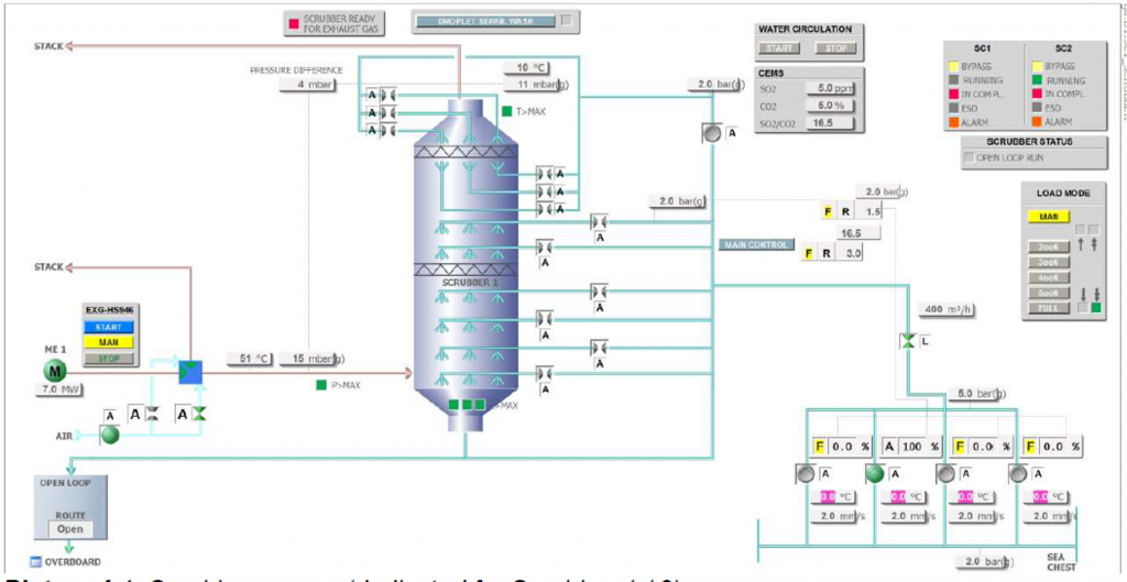
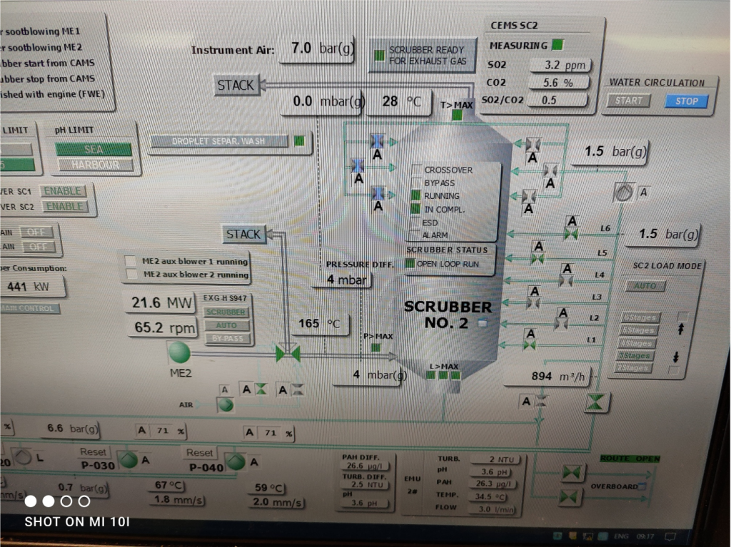
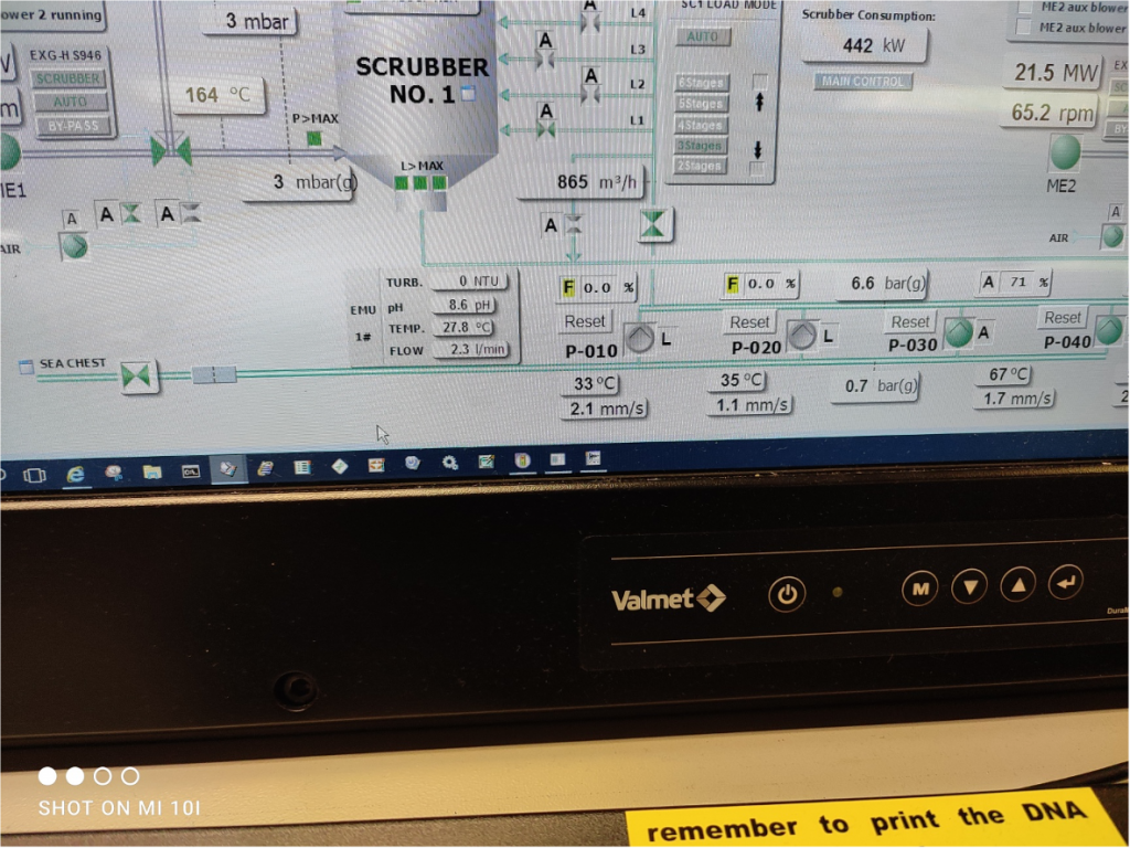
OPEN LOOP SCRUBBERS
•In open loop mode seawater is used as wash water. Exhaust gas SO2 reduction is based on natural alkalinity of the seawater.
•Natural chemical compounds in seawater will react with SO2 that is captured from exhaust gas to scrubbing wash water.
•To reach efficient SO2 reduction with open loop mode, higher water amount is required, as no additional chemicals are added in open loop circulation.
•Open loop mode is optimised by controlling the amount of running pumps according to reached emission limits and engine power.
MAIN COMPONENTS
•Sea Water Pumps
•Separator Wash Pump
•3-Way By-Pass Valve
•Sealing air fans
•CEMS(Continuous Emission Monitoring System) WMS(Water Monitoring System)
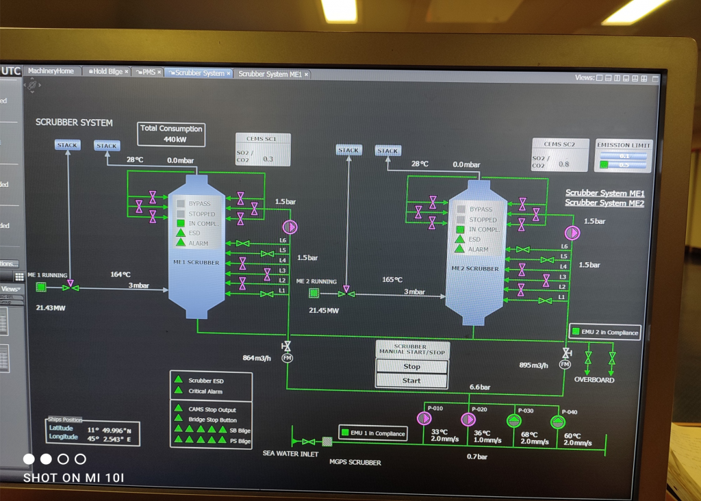
Sea Water Pumps
•In open loop three seawater pumps are running and pumping seawater to scrubber tower nozzle stages.
•There is automatic selection of running/standby pumps based on pumps’ running hours.
•In case of failure of any pump in open loop, the system will automatically start an idling pump.
•Pumps are started/stopped automatically by scrubber start/stop sequences.
Separator Wash Pump
•Separator wash pump is running during open loop operation when at least one sea water pump is running and there is enough pressure on the highest washing stage.
•The pump is started/stopped automatically according to the droplet separator wash valves’ open commands.
3-Way Bypass Valve
•3-way damper is opened to scrubber when exhaust gas from engine needs to be treated.
•3-way damper is opened to bypass after engine is stopped (after a delay).
•If compliant low sulphur fuel is used and SO2 reduction from exhaust gas is not needed, it is possible to keep 3-way dampers open directly to funnel by stopping the scrubber system completely.
SEALING AIR FANS
•Sealing air fan is running always when engine is running, which will prevent exhaust gas to enter funnel in any situation.
•Fan stops if engine is stopped (after a delay).
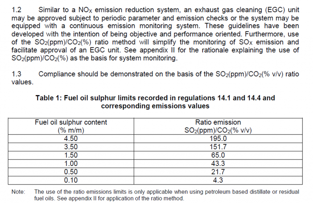
CEMS
•CEMS can monitor the SO2 and CO2 concentrations in exhaust gas according to the requirements in IMO regulations – NOx Technical Code 2008 and the requirements in MEPC.259(68).
•It provides an accurate measurement of SO2 in ppm, CO2 in percent and the SO2/CO2 ratio
CEMS
•The system consists of a multigas analyzer with a sampling and sample conditioning system.
•The gas analyzer is based on a non-dispersive infrared measurement technology.
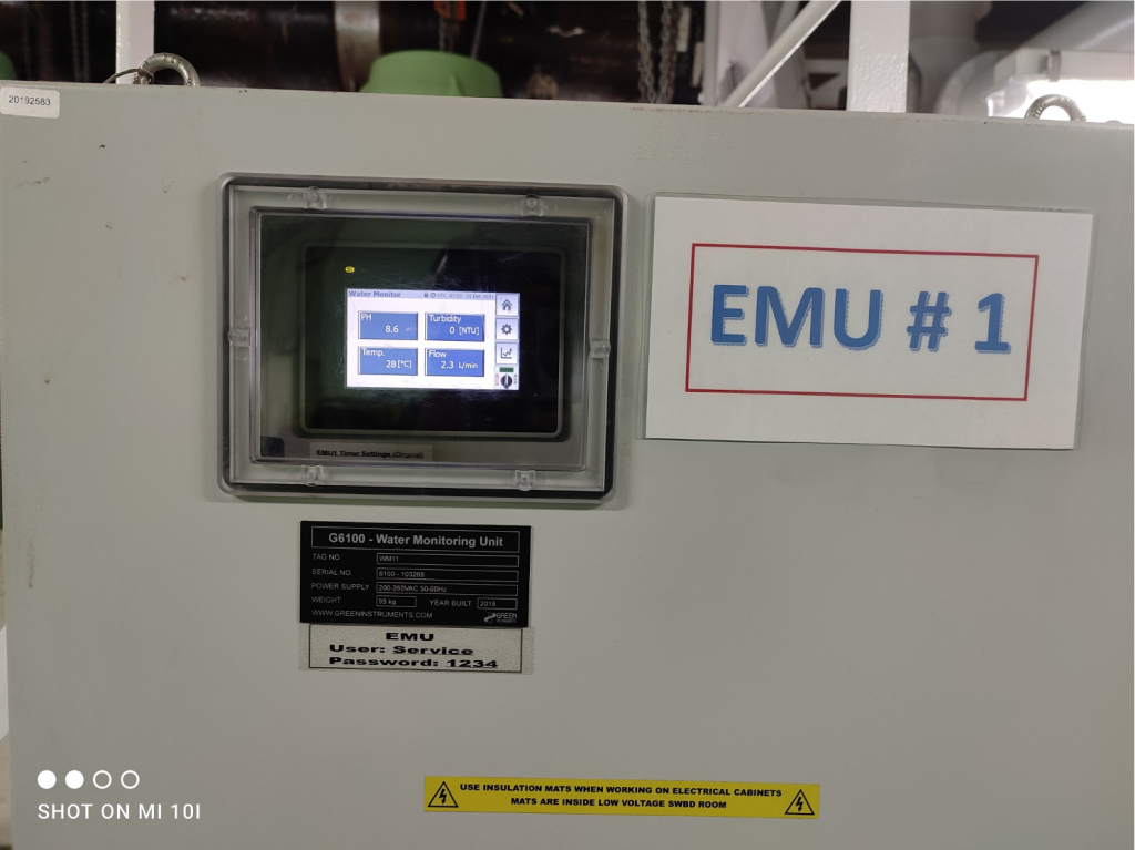
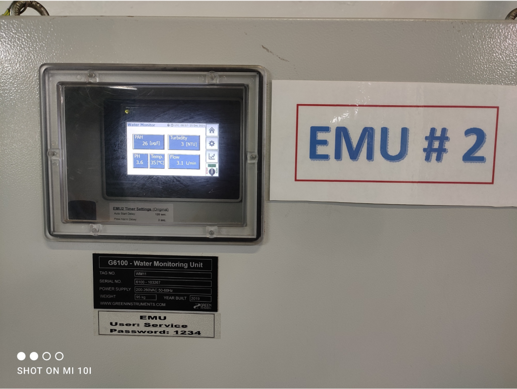
WMS
•The water monitoring system is an operator station with a sampling system which supplies the integrated sensor modules.
• The sensor modules measures PAH, turbidity, pH and temperature.
•The PAH Module measures the content of PAH in water as a phenanthrene equivalence as specified by MEPC.259(68). The technique used is UV induced fluorescence with the capability of detecting μg/l (ppb) in water.
•The Turbidity Module measures the turbidity of water in accordance with MEPC. 259(68).
•The technique used is 90° IR Scattering in accordance with ISO7027.
•The Turbidity Module can detect sooth, particles and suspended soil in the water.
•The pH/Temperature Module measures the pH value and temperature of the water.
•Temperature compensation and self-cleaning ensures accurate and reliable measurements in varying conditions.
MEPC 259(68)
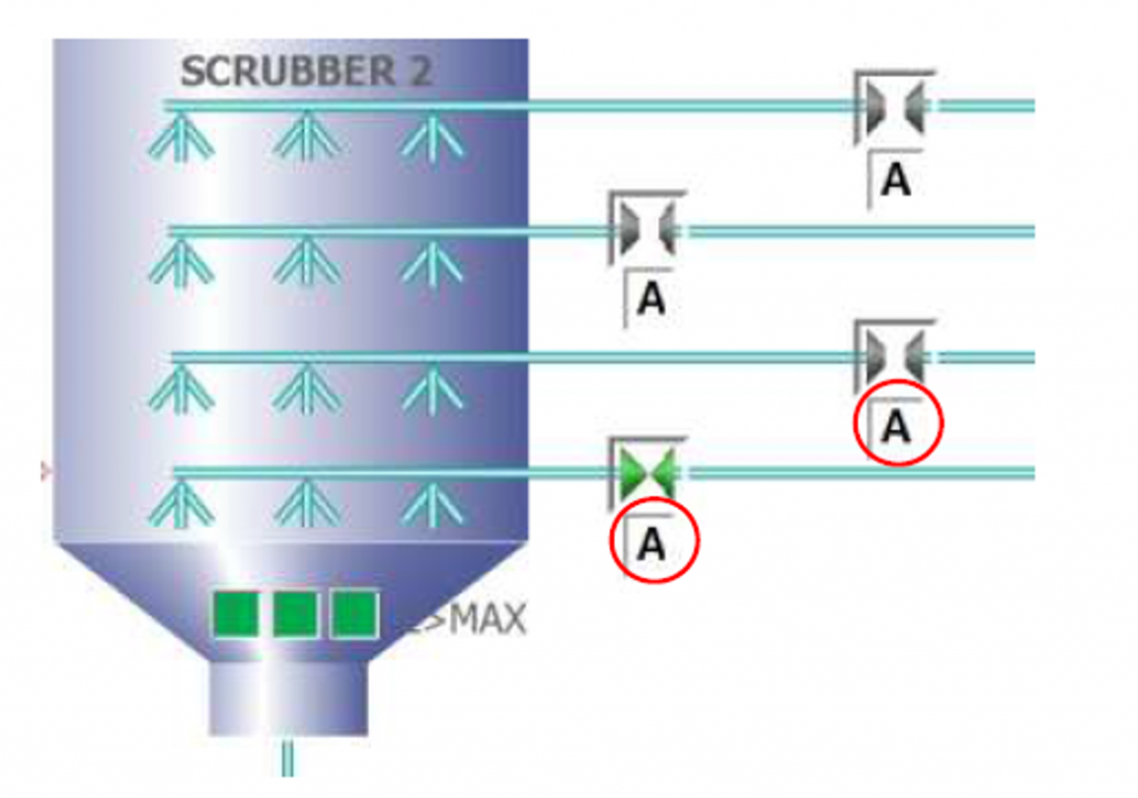
Auto Valves & Nozzles
MAINTENANCES AND CHECKS
•Daily measures:
•Visually inspect condition of all rotating equipment (pumps and fans). Ensure that abnormal sounds do not exist and pumps are not vibrating (vibration values for the seawater pumps are available in the DCS). Buzzing sound may indicate a leakage. Clattering sound may indicate a broken equipment or unwanted object inside the equipment/piping. Source of abnormal sound must be found and corrective actions to be performed.
•Check that there are no leakages from pipes or pumps.
•Check motor temperatures by hand. Temperature values for the seawater pumps are also available in the Scrubber console. •Check that readings in local pressure gauges, and level and temperature meters are correct and in line with other measurements.
•Weekly measures:
•Record all readings of local gauges and meters in a record book. This will help to analyse afterwards if there is tendency for any parameter to change over the time. Information and trends available in scrubber console.
•Check condition of pH sensors. Take water sample and check using pH paper or use boiler water analysing kit, whichever is more accurate. Perform the action for all pH sensors. Calibrate if necessary. Note! pH sensors must to be stored wet when taken out from the process!
•Monthly measures:
•1. Inspect and maintain scrubber (corrosion, solids deposits, dirtiness). Remove all •solids deposits and clean surfaces.
•2. Check bottoms of scrubber wash water drain channels (2 pcs, located at scrubber •bottom part) and for accumulated dirt and clean if necessary.
•3. Check condition of nozzles (clogging, unwanted objects, corrosion) and clean if •necessary. Remove and replace with new nozzle if necessary.
• 4. Check operation of manual valves. Turn them to both extreme positions (while •process is stopped).
•5. Inspect condition of droplet separator and droplet separator washing. Remove •soot and dust deposits and clean with pressurized water from both sides, if •necessary.
•6. Inspect condition of piping (leakages, corrosion).
•7. Check condition of flexible joints. Replace if necessary.
•8. Check and calibrate pH sensors. Replace pH probe if necessary.
•9. Check water monitoring sensors
•Yearly measures:
•1. Check and maintain exhaust gas dampers (see damper supplier’s O&M manual).
a. Visual inspection
b. Remove soot deposits
c. Check operation of dampers (incl. safety bypass operation)
d. Check that dampers open / close completely
e. Lubrication
f. Check gaskets and replace if necessary •
•2. Check and maintain all pumps (see pump supplier’s O&M manual)
a. Check clearance and fits
b. Check gaskets and replace if necessary •
•3. Check and maintain all sealing air fans (see fan supplier’s O&M manual)
a. Check clearance and fits
b. Check gaskets and replace if necessary •
•4. Replace pH probes with new probes.
•5. Calibration of water monitoring sensors
•6. Calibration of CEMS units

 REQUIREMENTS")
