

Modern A.V.R. (Zener Bridge)

- Voltage through the Zener diodes remains almost constant independent of current variations.
- Smoothed D.C. output is applied to the voltage reference bridge.
- This bridge is balanced at the correct generator voltage output with no potential difference between A & B.
- If the generator voltage fails, current through the bridge arms falls & current flows from A to B through the amplifier.
- If the generator voltage falls, current across the bridge arms falls and current flows from B to A through the amplifier.
- If the generator voltage rises, Current across the bridge arms rises with current flow from A to B through the amplifier.
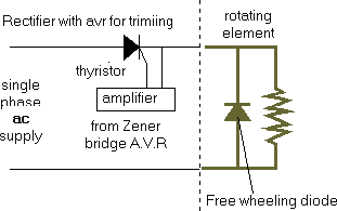
- The signal from the amplifier will automatically change the field excitation current, generally through a silicon controlled rectifier (Thyristor) control element.

- The Silicon Controlled Rectifier(Thyristor) is a 4 layer, 3 terminal, solid state device with the capability to stop the flow of current, even when forward biased, until the gate signal is applied.
- This gate signal could come from the Zener diode Voltage reference bridge.
- The gate signal will switch on forward biased S.C.R.(silicon controlled rectifier) & current pass across the exciter field.
- When reverse biased the S.C.R.( silicon controlled rectifier)will again stop the current flow.
- Due to inductance of the field winding the S.C.R.(silicon controlled rectifier) would continue to pass the current for the part of the negative cycle.
- By fitting a ‘free wheeling’ diode the current across the Thyristor falls quickly at the end of the positive cycle.
- In some circuits the excitation current is made to be in excess of requirements, so that the gate signal decreases flow.

 REQUIREMENTS")
