

CYLINDER DISTANCE
In a slow-speed 2-stroke engines the cylinder distance & consequently engine length are invariably decided by the powertrain layout, which takes place in parallel with thermodynamic layout. Cylinder distance determination is central to engine development since it gives the geometrical boundary conditions for most other design groups. Figure below shows a cross section of the crankshaft and the cylinder distance, which comprises:
- The width of the crankpin bearing(Wcrankpin bearing), which is primarily determined by the maximum firing pressure & minimum engine speed
- The width of the main bearing(Wmain bearing), which is normally laid out according to engine power, speed & rotating masses of crankshaft & connecting rod
- The shrink fit length, which depends upon the required transmissible torque, web geometry, journal diameter & crankshaft material.
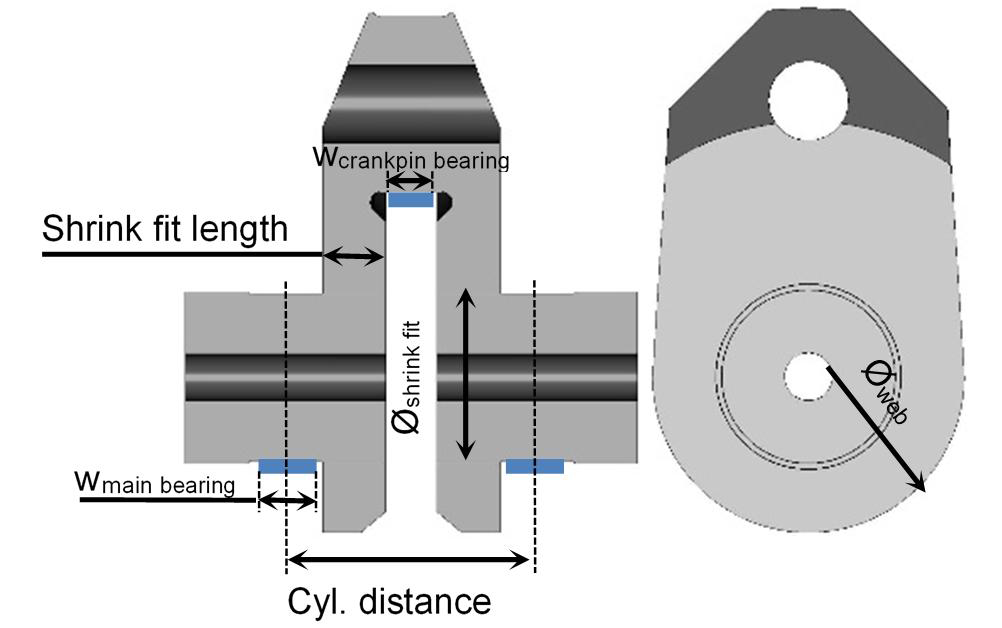
The selected cylinder distance is verified against other the possible influences, such as connecting rod thickness, crosshead bearing or cylinder cover arrangement(bolts, valves). Historically, 2-stroke engines have had uniform cylinder distance, but modern engines such as the Wärtsilä-X92 have variable cylinder distance
DEVELOPMENT PROCESS
The development of engine powertrain goes hand in hand with the engine structure, since the forces from the crankshaft affect the structure & in turn the behaviour of the structure influences the powertrain. An easier description of the development process for the powertrain & engine structure is laid out in the following steps:
- Based on the bore, stroke, rating field & cylinder pressure specifications an initial estimation is made for width of the main bearing, crank web(shrink fit length) & crankpin bearing, which gives the first cylinder distance
- In parallel, gas excitation files for the new engine are developed from the cylinder pressure curves at various points on the rating field
- Later, with an assumed shaft line & propeller for a suitable marine installation, first dynamic calculations are done to evaluate the main powertrain dimensions
- A first stress calculation of the new engine structure(bedplate & column) can then be carried out in order to determine the main structure dimensions
- If evaluation of the dynamic behaviour for the crankshaft is accepted, then detailed layout & design of crank train are carried out
- Based on final crank train data & updated engine structure, the optimization of firing order for the crankshaft in regards to free forces & moments & crankshaft vibrations is started. Results of Elasto-hydrodynamic (EHD) calculations for the bearings are considered.
- After determination of all crank train parameters, a final stress & strain calculation for the engine structure can be performed.
CONCEPT, DESIGN AND MATERIAL CHOICES
Throughout this development process the engine designer is confronted with numerous choices for design concepts, trade-offs and material choices, the most important of which are described below:
- Engine height vs. width: There exists a clear trade-off between crankshaft centreline height(which affects total engine height) and bedplate width for a given stroke, illustrated below:
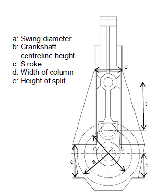
A higher crankshaft centreline height(b) permits a narrower(lower part) bedplate width but results in the higher overall engine height. The bedplate side walls are often slanted in order to optimise the width at the bottom but still allow for enough space for the swing radius (a) at centreline height.
The total height of a modern 2-stroke marine Diesel engine is normally approximately 3.5 times engine stroke, and depends on: stroke, crankshaft centreline height, connecting rod and stuffing box design. The piston dismantling height is about 4.5 times the stroke.
- Crankshaft: Low speed 2-stroke engine crankshafts differ from crankshafts in other engine segments in two main characteristics: i) the semibuild construction due to limitations of casting and forging for such sizes and strokes, ii) the materials used. The crankshaft layout is first & foremost based on the basic recommendations given by the classification societies for semi-built crankshafts depends on the input parameters such as engine power & torque, torsional vibration limits, geometrical parameters such as the shrink fit diameter, etc. There are two basic materials typically used for the semi built crankshafts, namely a carbon steel(M60.6) & an alloyed steel (34CrNiMo6) with a higher yield strength.
- Bedplate: The 2-stroke marine Diesel engine mostly consists of a welded structure, which is preferred to cast structures for reasons of size & production volume. The most important design choice for the bedplate, the lower structure part, is single or double wall design. A single wall bedplate is more flexible to tilting of the main bearing housing, but introduces other challenges such as the fixing of the tie rods to the girder. An important design feature of the bedplate is the thrust bearing, laid out to withstand the vessel’s thrust, which consists of a certain amount of pads arranged in an incomplete circle. The angle where the pads can be placed is limited by the flexibility of the structure, and the total bearing area is determined by the lining material used and the expected dynamic thrust. significantly, the vertical position of the geometrical centre of the thrust bearing influences the tilting of the thrust bearing shaft & thus also the load distribution of the neighbouring main bearings as well as the intermediate bearings of the propeller shaft.
- Column: Similar to the bedplate, the column, which is “sandwiched” between the bedplate and the cylinder block, can be single or double walled. The single wall design, which is normally simpler to produce, is mostly influenced by the guide shoe lateral forces. An additional design choice is the fixation of the tie rods, which are four per cylinder for the single wall column design & two per cylinder for double wall design(placement of tie rods between the walls).
- Bearings: The bearing forces are the main drivers of the stresses in the bearing, whereas conversely the stiffness of the housing is influencing the bearing behaviour. The interaction between bearing housing and the crankshaft is calculated by EHD calculation. Depending upon the bearing location there are different influence parameters & challenges. First & foremost, the main bearing can be subject to high edge load such that a certain flexibility for tilting of the bearing housing is beneficial. On the other hand, crosshead and crank pin bearings do not face any inclination of the bearing pin but some other challenges such as low hydrodynamic speed and pin lift-off. For the crosshead bearing there are some additional restrictions caused by the space availability for part dismantling(e.g. guide shoe) & removal out of the engine (e.g. the maximum diameter of the crosshead pin is constricted by the width of the column doors)
- Oil supply to piston & crosshead bearing: The oil supply for the connecting rod bearings and for the piston cooling system is ensured on most Wärtsilä engines by the knee lever. The structure of the knee lever can accomodate a twin circuit system, which allows the differentiation of the pressure level for piston cooling from crosshead bearing lubrication oil. This feature is increasingly important since higher firing pressures are needed to optimise SFC, which increase the load on the crosshead bearing above the limit for a given diameter. This limit is increased by applying high pressure crosshead bearing oil supply.
MANUFACTURING LIMITATIONS
Due to the sheer engine size of the largest engine models (such as the Wärtsilä X92), manufacturers often come to size limitations with several components, such as, but not limited to:
- Crankshaft size & weight: Foundry capacity(the crankshaft webs are free-forged out of one ingot, & capacity of the largest foundries is approx. 60 tonnes nowadays), rough & final machining lathe size(limited by the stroke), & crankshaft weight due to crane capacity limitation for the crankshaft assembly at manufacturer & engine assembly at licensee.
- Bedplate size: the welded two-stroke bedplate is Post-Weld Heat Treated (PWHT) to remove residual stresses from welding, creating a limitation for large engines due to the size of the PWHT oven.
- Column height: the column height, which is determined by the engine stroke, is limited by the size of the Plano-miller for the milling of the crosshead guide rails (the counterpart of the guide shoe).

 REQUIREMENTS")
