

When steel is immersed in sea water (e.g. a ships hull) small galvanic current are initiated at anodic areas of the metal surface, causing corrosion.
Such corrosion prevail at the stern of a ship, where the combined effects of increased turbulence and differential metals results in accelerated corrosion rates.
The application of Cathodic Protection effectively suppresses these corrosion cells by supplying an opposing current from external anodes and if the propeller is to take the benefits of cathodic protection then there should be a continuous electrical circuit between the propeller and the ships structure.
This circuit normally exists when the propeller is at rest, where a metal to metal contact is made between the shaft and the stern tube liners, or main engine bearings and journals.
However, while the shaft is turning the bearing lubrication creates an
irregular high resistance which effectively insulates the propeller from the hull structure and therefore the propeller presents a relatively large surface area of pure metal, it attracts cathodic protection currents, which tend to discharge by arcing across the lubrication film results in spark erosion which eventually leads to pitting and ‘striping’ of white metal
bearing surfaces.
It is generally accepted, that the effects of arcing are minimised when the potential difference the shaft/hull interface is less than 50 mV.
To overcome this undesirable condition of arcing, whilst at the
same time ensuring that cathodic protection is extended to the propeller, it
is a general practice to install Shaft Bonding equipment as an integral
part of a ships Cathodic Protection system and is applicable in
conjunction with both sacrificial anode schemes as well as the Impressed
Current technique. Furthermore, where such bonding is installed it is
recommended that the capacity of the cathodic protection system should
include an allowance for the propeller.
Different combinations of slip ring and carbon brush materials are available but according to experience only high silver composition brushes running on a silver track, can give the effective and sustained low
conductivity required to ensure that the shaft bonding and its connections
maintains a contact resistance not greater than 0.001 Ohms.
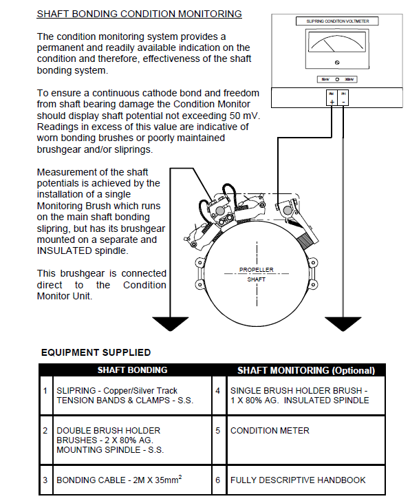
However, it is accepted that in practice, such a low value is outside the range of most commercial multimeters and is therefore difficult to determine. It is for this reason thats why many ship operators prefer a permanent visual indication in the form of a shaft condition monitor, which gives a constant display of shaft potential and confirmation that the bonding equipment is successfully maintaining this at a level not exceeding the optimum value of 50 mV.
The M G DUFF system of shaft bonding comprises a split slipring arrangement and ancillary brush gear, which is designed to facilitate ease of assembly by proficient technical personnel and without the need for specialist tools.
The slipring is supplied as two identical halves rolled to the specified shaft diameter. However, to allow a tolerance for difference in shaft diameter the slipring is manufactured slightly oversize and should be dressed to fit on site. This involves take out small amounts of metal at the slip ring mating joints until an exact fit is achieved and the slipring conforms to the shaft diameter without unevenness. Failure to remove excess slipring material before securing with the band tensioning, or to finish with badly fitted joints will resultin distortion or an uneven track surface with consequent rapid brush wear.
Under normal circumstances, a correctly fitted slipring and associated brushgear can be expected to perform for many years and with a minimum maintenance requirement. Under these condition and related to the vessels trading pattern, the anticipated brush life is one year, although smaller diameter shafts turning at higher brush contact speeds will inevitably result in increased brush wear rates.
To ensure effective bonding, the slipring should be installed on the intermediate shaft, astern of any insulating couplings or flanges and preferably clear of water spray or oil and grease contamination from stern gland lubrication.
When ordering please specify:
- Shaft Diameter
- Number of Shafts

 REQUIREMENTS")
